Grinding wheel

a technology of grinding wheel and cutting body, which is applied in the direction of gear teeth manufacturing tools, grinding machines, gear teeth, etc., can solve the problems of poor penetration behavior of cutting body, rapid reduction of tool output, and inability to self-sharpen hard metal elements, etc., and achieves the effect of facilitating material removal and increasing grinding outpu

Inactive Publication Date: 2005-08-09
HILTI AG
View PDF10 Cites 8 Cited by
  • Summary
  • Abstract
  • Description
  • Claims
  • Application Information

AI Technical Summary

Benefits of technology

[0009]The arrangement of the cutting bodies according to the present invention permits the achievement of a wedge-like removal of the coating material. The wedge-like penetration of the cutting bodies into the coating insures a more rapid removal of the coating material from a constructional component, without the coating being heated and without the coating material sticking to the cutting bodies. A particularly high output is achieved when the longitudinal side forms with the radial line an angle of about 45°. Moreover, the good penetration behavior of the cutting bodies with respect to the coating results in smooth running of the grinding operation.
[0012]Advantageously, the grain size of the diamonds in the first matrix zone is smaller than the grain size of diamonds in the second matrix zone. This leads to a different wear of the diamonds during a grinding operation. In the first matrix zone, the diamonds do not break out as rapidly as in the second matrix zone. Even when the diamonds of the first matrix zone break out, this does not result in a non-sharp edge because of the small size of the grains in the first matrix zone. Because of their comparatively large size, the diamonds in the second matrix zone break out more rapidly than in the first matrix zone. Therefore, a greater wear of the support back face which is built-up during the grinding operation, takes place. Thereby, the cutting edge of the cutting body assures a certain “free position”.
[0014]In order to insure that grinding is effected with the entire grinding region, the grinding region is formed of a plurality of radially offset, at least partially overlapping each other, coaxially arranged circular surfaces, with at least one cutting body being located in each of the circular surfaces. The grinding output is increased when the cutting bodies are inclined toward the plane of the grinding wheel. The inclination of the cutting bodies to the grinding wheel plane facilitates removal of the material because the removable material contacts not a perpendicular surface but rather an inclined surface of the cutting body and is separated from the constructional component at a so-called effective cutting angle. The inclined surface is formed by the longitudinal side of the cutting body which extends to the plane of the grinding wheel, which is defined by the plane of the grinding region, at an angle from 80° to 90°. With the inclination angle of 80°-90°, an effective cutting angle, which is formed between the longitudinal side and perpendicular to the grinding wheel plane, of from 10° to 20° is obtained. It is particularly advantageous when the effective cutting angle amounts to 15°.
[0015]Good removal of the coating material from the cutting region is effected through openings formed in the grinding region of the grinding wheel. Advantageously, a through-opening is provided in a circumferential region of each cutting body opposite the cutting edge of the cutting body. The advantage of such an arrangement of the through-openings of the grinding region consists in that the coating material can be removed immediately after cutting by a cutting body, e.g., by using a suitable suction device that would aspirate the material from the operational region.

Problems solved by technology

The drawback of such a tool consists in that no selfsharpening of the hard metal elements takes place.
Therefore, the output of the tool becomes rapidly reduced during the service life of the tool.
Such cutting results in a poor penetration behavior of the cutting body with respect to the coating and leads to an increased heating of the coating which is caused by friction between the coating and the rotatable cutting body.
The increased heating leads to weakening of the coating and to adhesion of the removable material to the cutting body which leads to worsening of the penetration behavior of the cutting body with respect to the coating.

Method used


Image

  • Grinding wheel
  • Grinding wheel
  • Grinding wheel

Examples


Embodiment Construction

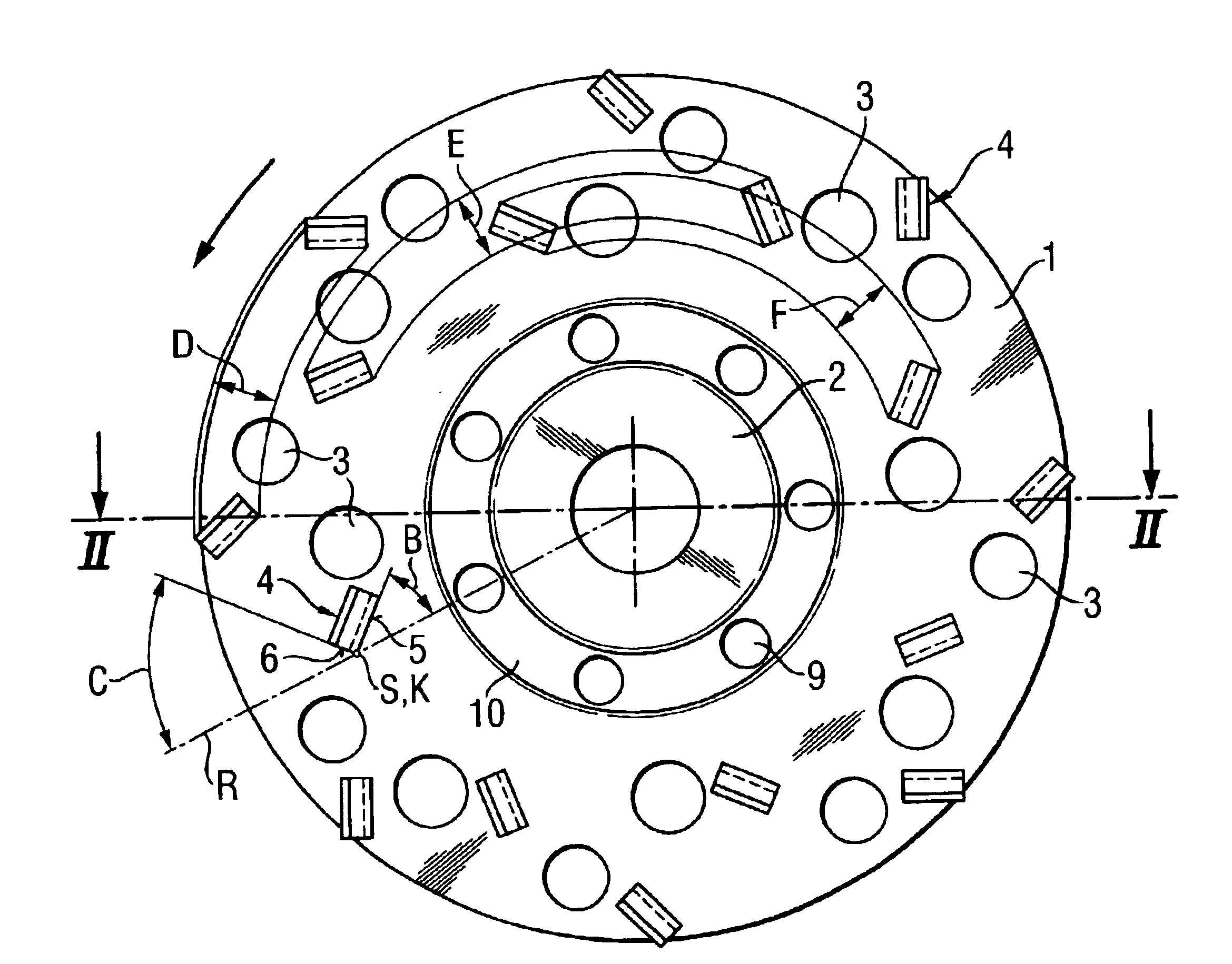
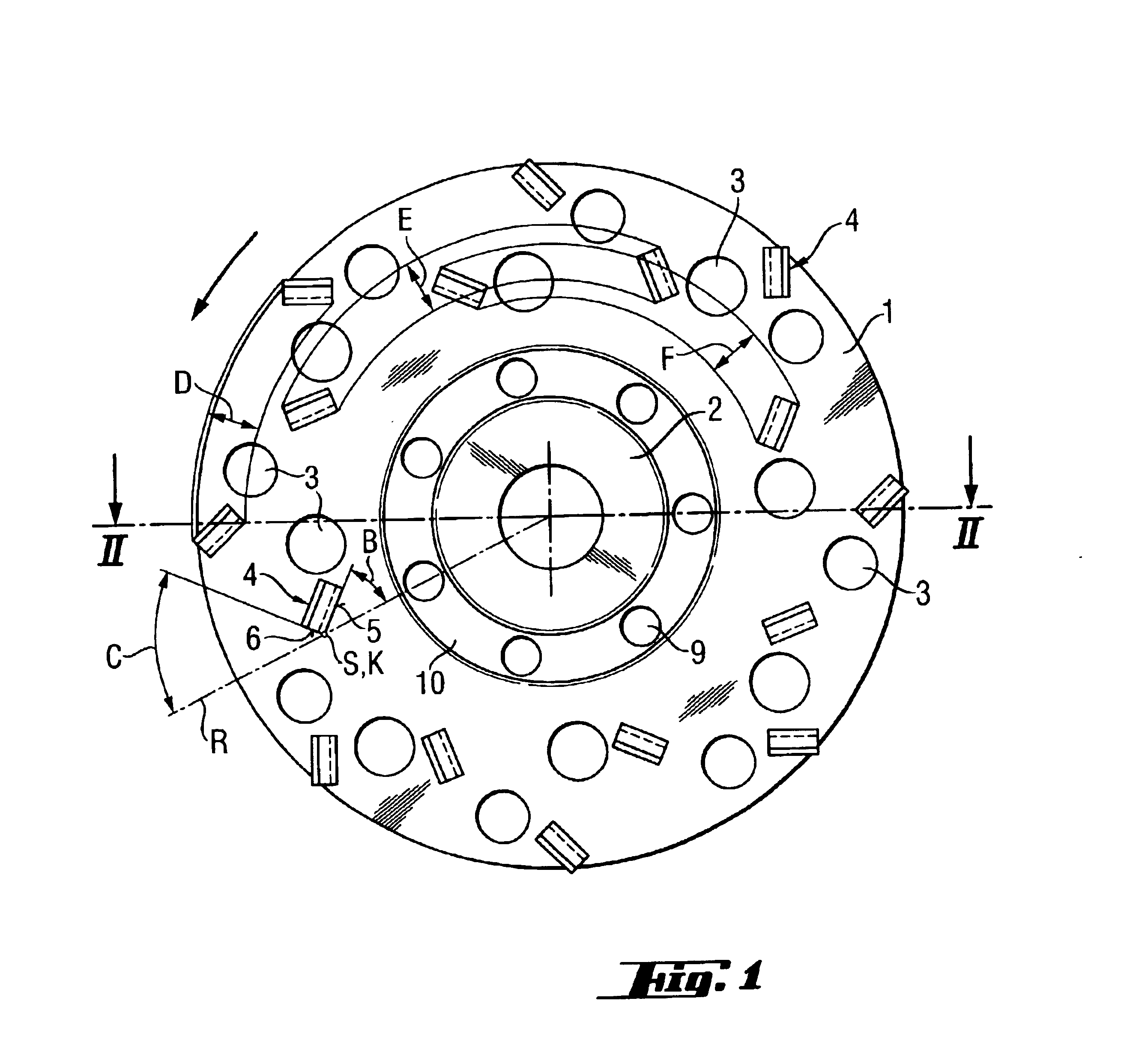
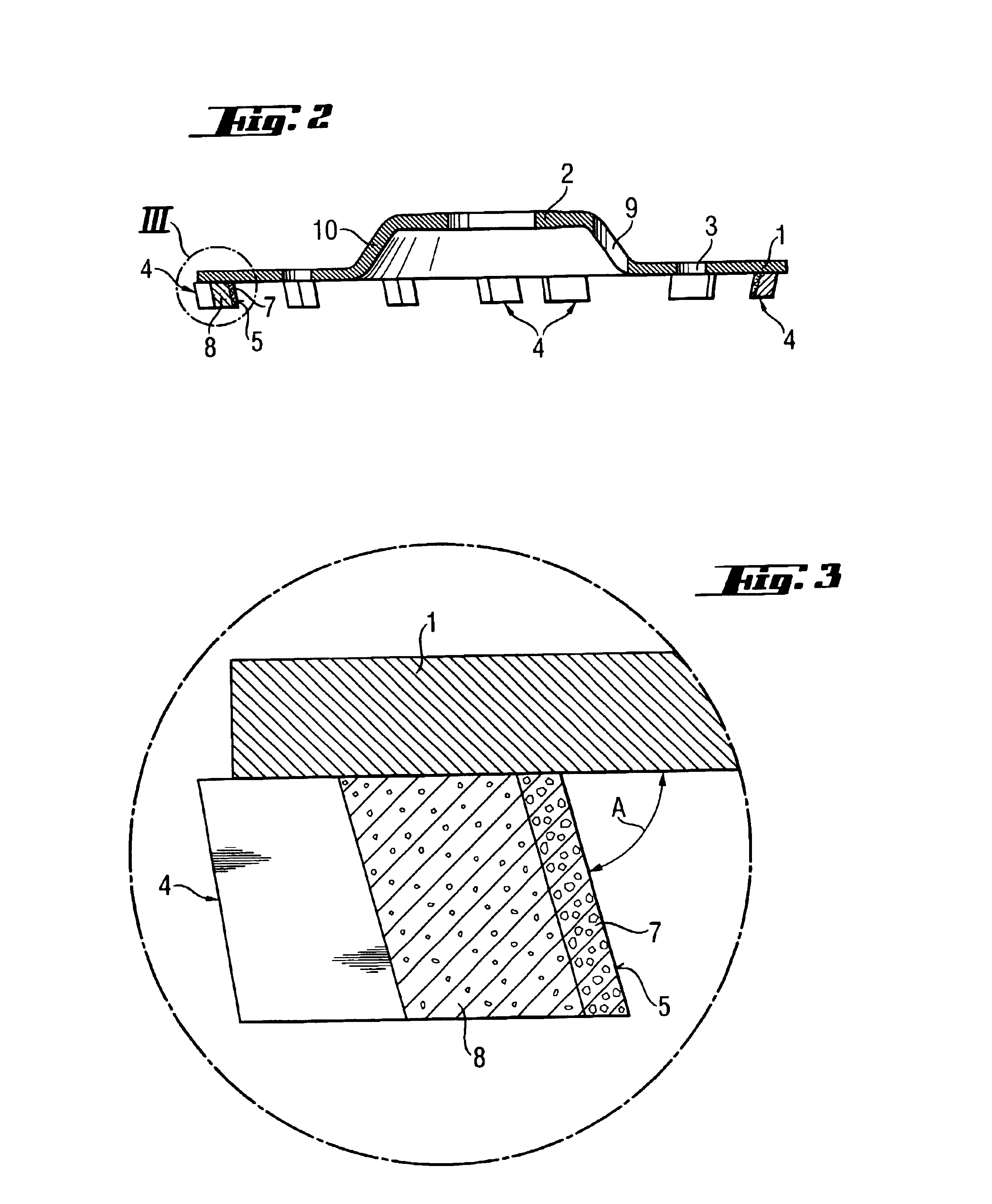
[0021]A grinding wheel according to the present invention, which is shown in FIGS. 1-3, is designed for removal of a coating from a mineral constructional component. FIGS. 1-3 show neither the mineral constructional component nor the coating. The inventive grinding wheel has a grinding region 1, a mounting region 2 located adjacent to the grinding region 1, a plurality of through-openings 3 formed in the grinding region 1, and a plurality of cutting bodies 4 which have a rectangular base surface and which project from the grinding region 1. The grinding region 1 and the central mounting region 2 are arranged coaxially with each other but are spaced from each other in a direction parallel to the common central axis of both regions 1 and 2. The transition region 10 between the grinding region 1 and the mounting region 2 has a conical profile. A plurality of through-openings 9 is formed in the transition region 10.

[0022]The grinding region 1 is formed of a plurality of radially offset ...


PUM


Abstract

A grinding wheel including a circular grinding region (1) with a plurality of through-openings (3) formed therein, a central mounting region (2) coaxial with the grinding region (1), and a plurality of cutting bodies (4) having a rectangular base surface, projecting from the grinding region (1), and spaced from a center of the mounting region (2) by different radial distances, with each cutting body (4) having a longitudinal side (5) adjacent to the center of the mounting region (2) and a wide side (6) remote from the center of the mounting region (2), with the longitudinal side (5) and the wide side (6) forming together an edge (K), and with the longitudinal side (5) extending at an angle (B) of from 35° to 55° to a radial line (R) extending from the center of the mounting region (2) and passing tangentially to the edge (K).

Description

BACKGROUND OF THE INVENTION[0001]1. Field of the Invention[0002]The present invention relates to a grinding wheel including a circular grinding region with a plurality of through-opening formed therein, a central mounting region coaxial with the grinding region, and a plurality of cutting bodies having a rectangular base surface, projecting from the grinding region, and spaced from the center of the mounting region by different radial distances.[0003]2. Description of the Prior Art[0004]For treating, e.g., coated surfaces of mineral constructional component, tools such as milling discs, which are provided with segment-shaped hard metal elements, are used. The drawback of such a tool consists in that no selfsharpening of the hard metal elements takes place. Therefore, the output of the tool becomes rapidly reduced during the service life of the tool.[0005]Also, are used grinding wheels equipped with diamond-containing cutting bodies which are particularly suitable for treating coated...

Claims


Application Information

Patent Timeline
Patent Type & Authority Patents(United States)
IPC IPC(8): B24D7/06B24D7/00B24D7/12
CPCB24D7/06B24D7/12
Inventor NUSSBAUMER, JOSEFSPANGENBERG, ROLFBOLAND, FRANCOISCHEVALIER
Owner HILTI AG
Why Eureka
Try Eureka