Thrombectomy device with multi-layered rotational wire

a thrombosis device and multi-layer technology, applied in the field of vascular devices, can solve the problems of vein failure, blood clot formation, and eventually damage to the vein beyond usability, and achieve the effects of improving the usability of veins, avoiding bleeding, and avoiding bleeding

Inactive Publication Date: 2005-08-09
ARGON MEDICAL DEVICES
View PDF145 Cites 159 Cited by
  • Summary
  • Abstract
  • Description
  • Claims
  • Application Information

AI Technical Summary

Benefits of technology

[0020]In one embodiment, the twisted wires of the inner core and the outer wire are composed of stainless steel, and at least some of the wires are heat treated at a temperature substantially less than 700 degrees Fahrenheit and substantially greater than 300 degrees Fahrenheit, and preferably about 500 degrees Fahrenheit, to retain the sinuous shape during rotation. The inner wires can be heat treated at a temperature and for a sufficient time that the sinuous shape is retained for at least about 5 minutes when the wire is moved through a test fixture consisting of a return bent tube having an inner diameter approximating the inner diameter of a hemodialysis shunt and slightly greater than the maximum width of the wire in the area of the sinusoidal shape, without loss of physical integrity of the wire.

Problems solved by technology

Since this approach requires multiple needle sticks in the vein to withdraw and return the blood, the vein can eventually be damaged beyond usability, blood clots can form and the vein can fail.
These agents, however, are expensive, require lengthier hospital procedures and run the risks of drug toxicity and bleeding complications as the clots are broken.
This multiple wire device is expensive and can be traumatic to the graft, possibly causing damage, since as the basket rotates at high speeds, the graft is contacted multiple times by the spinning wires.
Other risks associated with the basket include the possibility of catching onto the graft itself and tearing the graft as well as catching and tearing the suture at the anastomotic site.
Additionally, the basket can become filled with the clot which would then require time consuming withdrawal of the basket, cleaning the basket and reinserting it into the lumen.

Method used


Image

  • Thrombectomy device with multi-layered rotational wire
  • Thrombectomy device with multi-layered rotational wire
  • Thrombectomy device with multi-layered rotational wire

Examples


Embodiment Construction

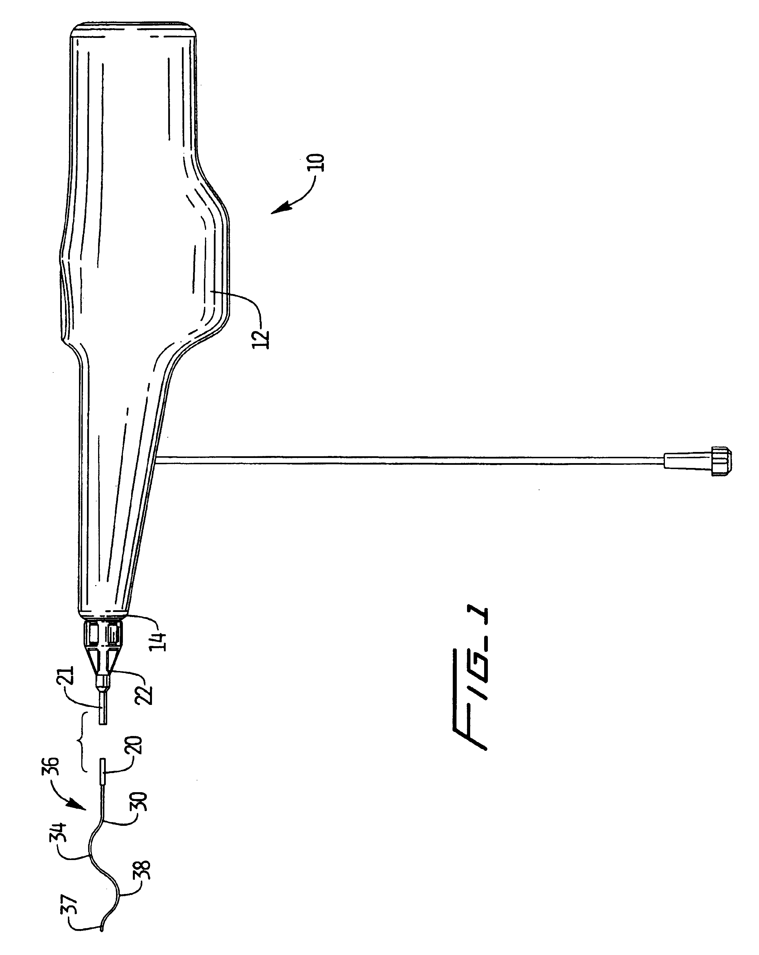
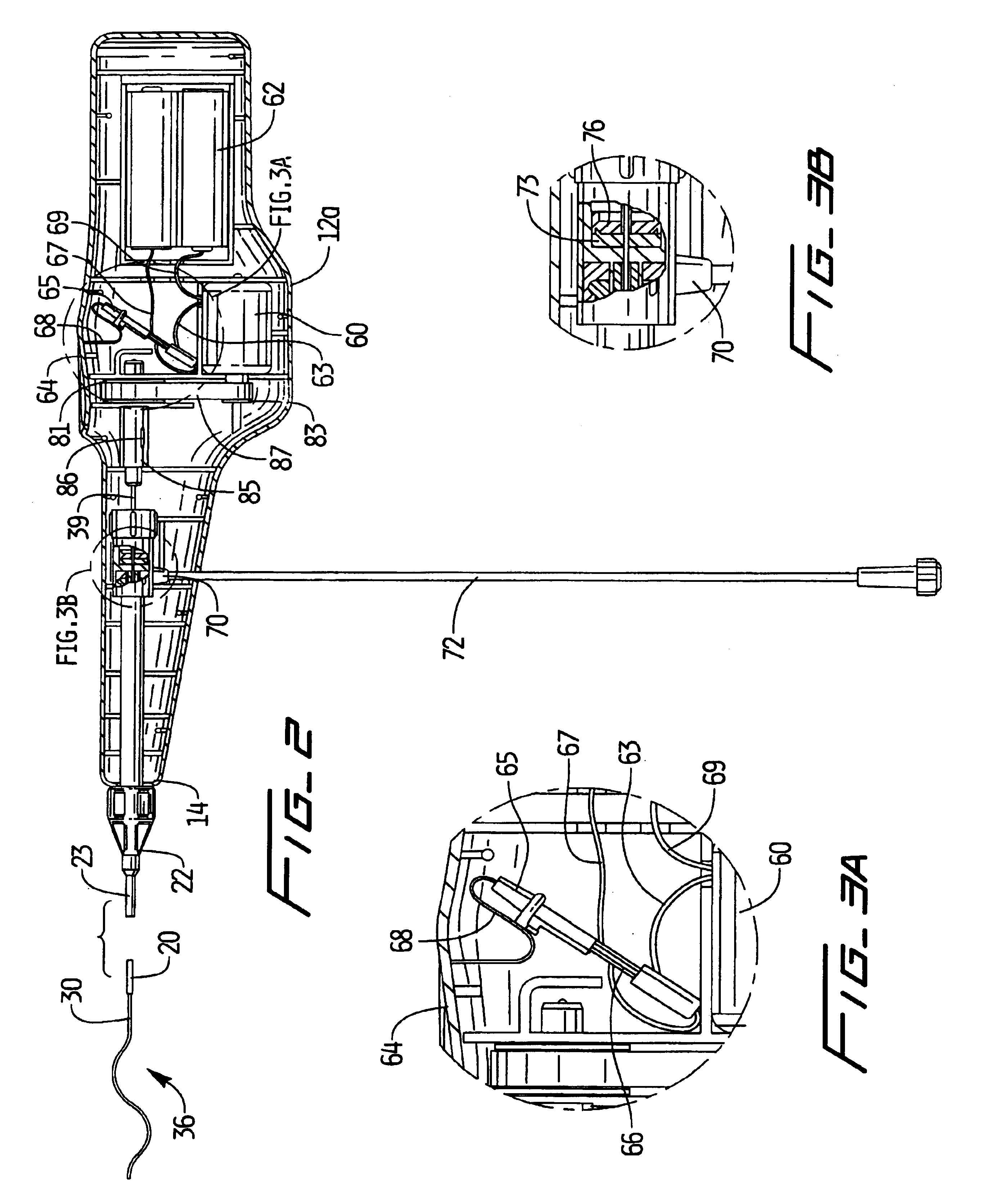
[0042]Referring now in detail to the drawings where like reference numerals identify similar or like components throughout the several views, FIGS. 1 and 2 illustrate the thrombectomy apparatus of the present invention. Apparatus 10 has a housing 12 composed of two housing halves, a flexible catheter (tube or sheath) 20 extending from a distal end 14 of housing 12, and a rotational thrombectomy wire 30. One of the housing halves is removed in FIG. 2 to illustrate the internal components of the apparatus 10.

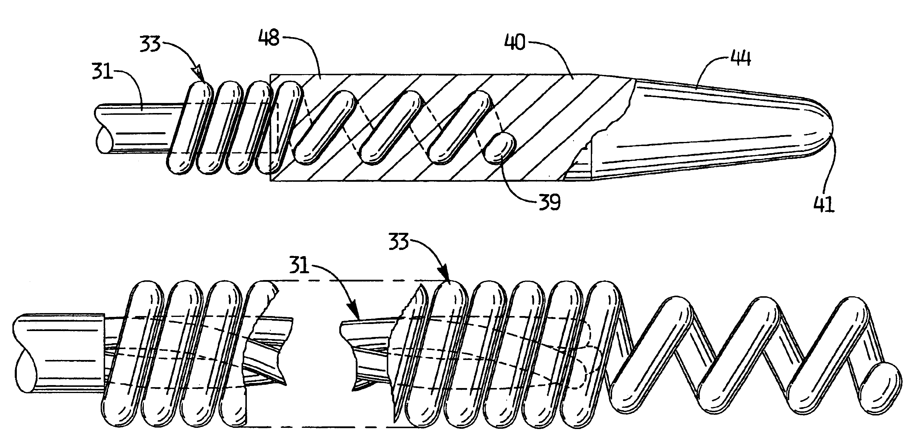
[0043]Wire 30 is sinuous in configuration, having a substantially linear region extending through most if its length, from a proximal region through an intermediate region until distal region 36. At the distal region 36, wire 30 has a first arcuate region 34 facing a first direction (upwardly as viewed in the orientation of FIG. 1) and a second arcuate region 38 facing a second opposite direction (downwardly as viewed in the orientation of FIG. 1). Thus, as shown, the wire 30 assu...


PUM


Abstract

An improvement to a thrombectomy apparatus for breaking up thrombus or other obstructive material in a lumen of a vascular graft or vessel having a wire and flexible sheath relatively movable, wherein the wire is sinuous in configuration and assumes its sinuous configuration when in the deployed configuration and has a straighter configuration in the first configuration. The wire is operatively connected to a motor for rotation of the wire to enable peaks of the sinuous wire to contact a wall of the lumen to break up the thrombus or other obstructive material. The improvement to the thrombectomy apparatus comprises the wire being formed of an inner core formed by a plurality of twisted wires and an outer wire wound directly around the inner core, wherein a distal portion of the outer wire extends distal of the inner core and progressively tapers towards a distal end to form a tapered region.

Description

[0001]This application claims priority from provisional patent application Ser. No. 60 / 369,953, filed Apr. 4, 2002.BACKGROUND[0002]1. Technical Field[0003]This application relates to a vascular device and more particularly to a thrombectomy device with an improved intravenous rotatable wire for clearing thrombus from dialysis grafts.[0004]2. Background of Related Art[0005]Hemodialysis is a well-known method of simulating renal (kidney) function by circulating blood. The kidneys are organs which function to extract water and urea, mineral salts, toxins, and other waste products from the blood with filtering units called nephrons. From the nephrons the collected waste is sent to the bladder for excretion. For patients suffering from chronic renal insufficiency, hemodialysis is life saving because it provides a machine to simulate the function of the kidneys, thereby enabling the patients to live independently between dialysis treatments.[0006]In the hemodialysis procedure, blood is wi...

Claims


Application Information

Patent Timeline
Patent Type & Authority Patents(United States)
IPC IPC(8): A61B17/22A61B17/00
CPCA61B17/320758A61B2017/00867A61B2017/22034A61B2017/22042A61B2017/22044A61B2017/320733
Inventor COOKE, DAVIDGEORGE, SUZANNE W.
Owner ARGON MEDICAL DEVICES
Why Eureka
Try Eureka