Control system and method for a magnetic indexer for high accuracy hole drilling

a magnetic indexer and high-accuracy technology, which is applied in the direction of twist drills, instruments, manufacturing tools, etc., can solve the problems of difficult, if not impossible, to precisely and reproducibly place a fastener between the two portions, create imprecise hole creation, and difficult to properly locate a fastener, etc., to achieve accurate positioning on the work surface

Inactive Publication Date: 2005-08-09
THE BOEING CO
View PDF16 Cites 55 Cited by
  • Summary
  • Abstract
  • Description
  • Claims
  • Application Information

AI Technical Summary

Benefits of technology

[0008]The present invention is directed to a control system for a magnetic indexer which locates a device that is producing a magnetic field in a blind or inaccessible position. A magnet is initially placed on one side of the work surface such that a magnetic field produced by the magnet extends through the work surface such that the axis of the magnetic field is substantially perpendicular to the work surface. The device, comprising a plurality of probes which are affected by magnetic fields, is positioned over the opposite side of the work surf

Problems solved by technology

In particular, if it is desired to affix together two portions of a structure, where only an outside surface is visible to a work person, it is often difficult, if not impossible, to precisely and reproducibly place a fastener between the two portions.
Once the skin is in place, it is often very difficult to properly locate a fastener that must first go through the skin to be affixed to the internal structure of the aircraft.
This, however, often creates impreciseness in the hole creation.
That is because the hole formed from the inside of the skin can not be easily formed exactly normal to the skin of the aircraft.
Furthermore, it is very hard on the work person who must crawl into the usually small areas to produce the hole

Method used


Image

  • Control system and method for a magnetic indexer for high accuracy hole drilling
  • Control system and method for a magnetic indexer for high accuracy hole drilling
  • Control system and method for a magnetic indexer for high accuracy hole drilling

Examples


Embodiment Construction

[0024]The following description of the preferred embodiment(s) is merely exemplary in nature and is in no way intended to limit the invention, its application, or uses.

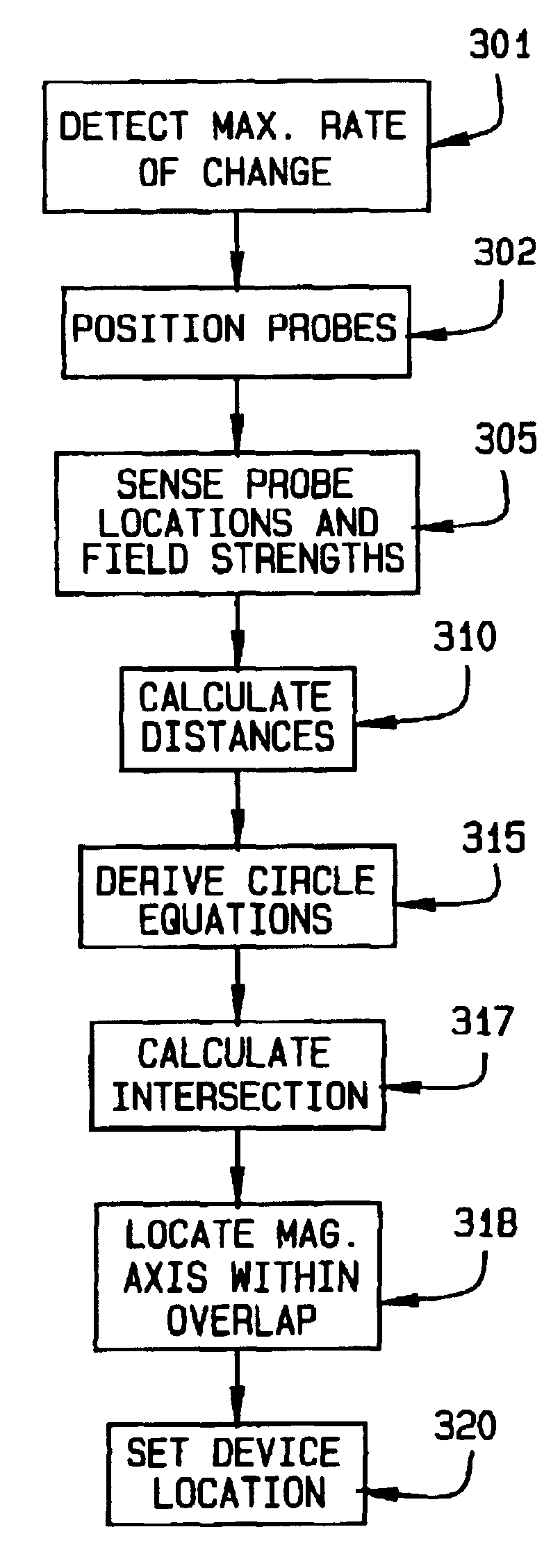
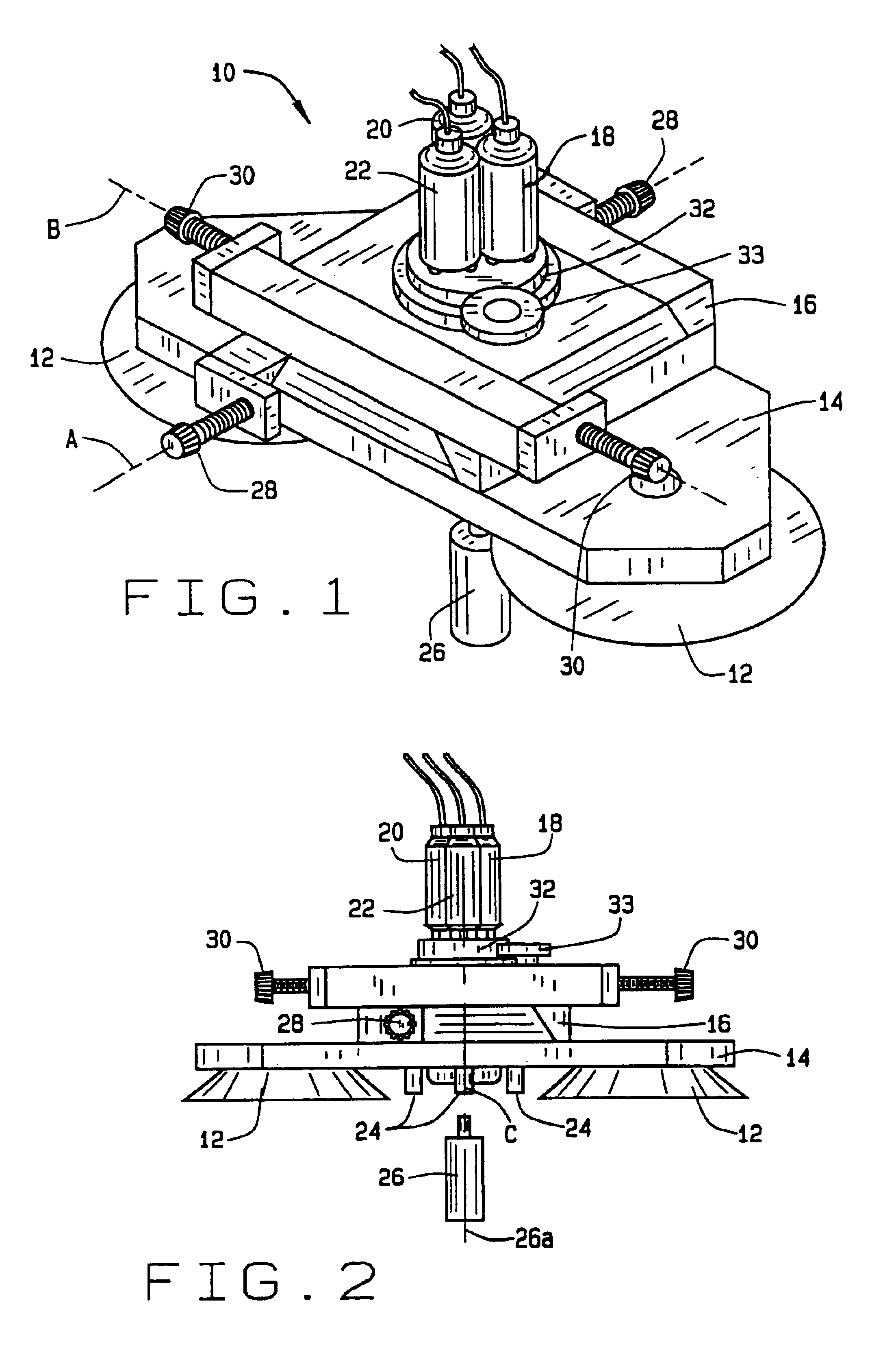
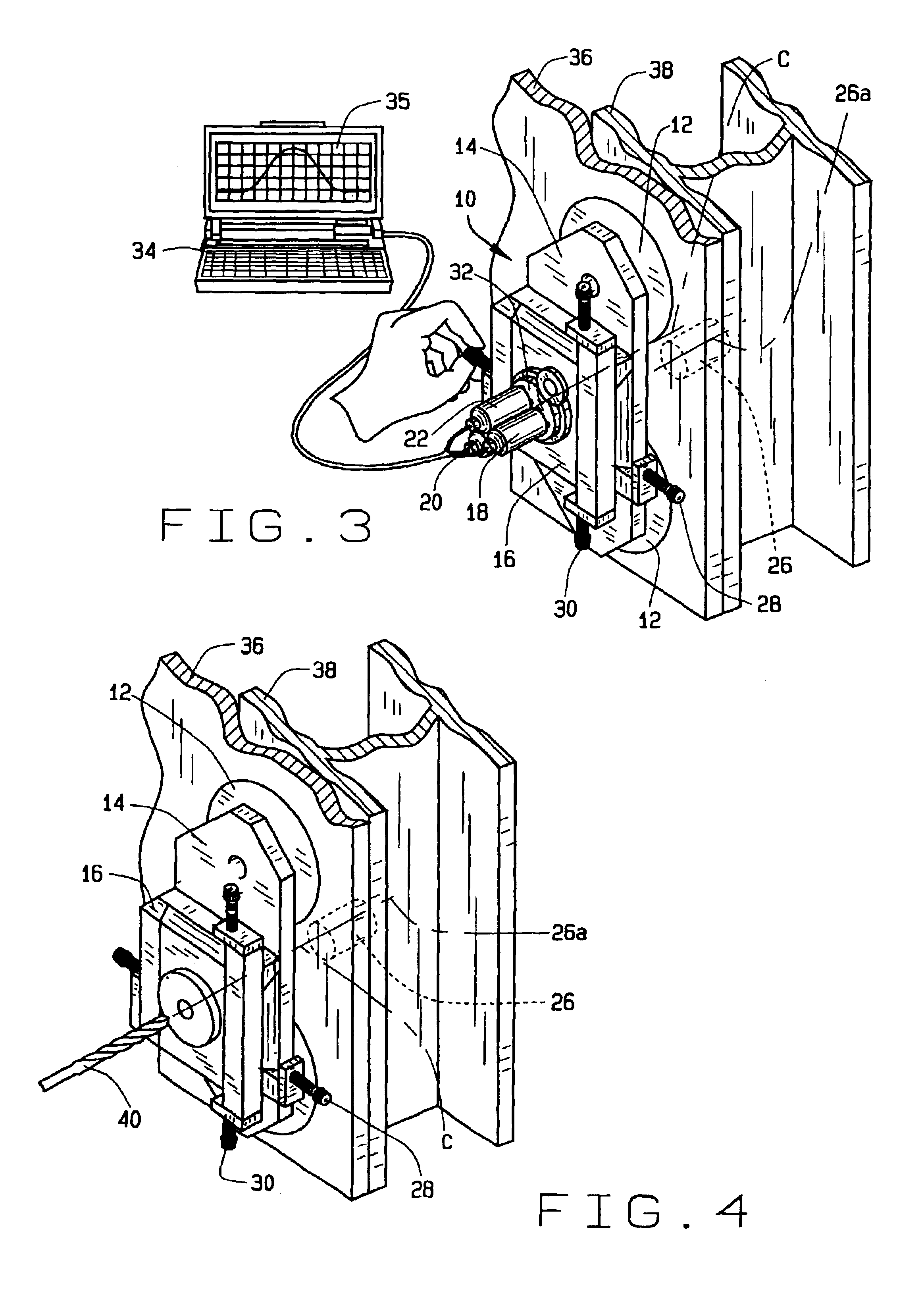
[0025]With reference to FIGS. 1 and 2, a magnetic indexer 10 in accordance with a preferred embodiment of the present invention is shown. The magnetic indexer 10 includes a vacuum attachment member 12, a work piece platform 14, a probe platform 16 and a plurality of probes 18, 20, and 22. The vacuum attachment member 12 generally includes members in which a vacuum may be created, so as to affix the work piece platform 14 to a work piece (described further herein). It will be understood, however, that any appropriate system suitable for attaching the work piece platform 14 to a work piece may be used.

[0026]Extending generally perpendicular from the work piece platform 14 are stabilizing members 24 (FIG. 2) which engage the work piece to ensure that the work piece platform 14 is substantially parallel to the work piece....


PUM

PropertyMeasurementUnit
Magnetic fieldaaaaaaaaaa
Strengthaaaaaaaaaa
Distanceaaaaaaaaaa

Abstract

A method for locating a device producing a magnetic field in a blind or inaccessible position of a work piece. A magnet is initially placed on a first side of the work piece such that a magnetic field produced by the magnet extends through the work piece. Probes are then positioned over a second surface of the work piece to determine the location of the axis of the magnet via the strength of the sensed magnetic field and the location where the strength measurements are made. Once the position of the axis of the magnet is determined, the work surface is either marked or worked on through the platform on which the probes are positioned. In particular, the present invention allows a very accurate positioning of a work tool on the second surface without the need to first visualize the first surface of the work piece.

Description

RELATED U.S. PATENT INFORMATION[0001]This application is a continuation in part of U.S. application Ser. No. 10 / 143,242 filed May 9, 2002, presently pending. The disclosure of which is incorporated herein by reference.FIELD OF THE INVENTION[0002]The present invention relates to a system to precisely form holes, and more particularly to a system to locate a device and indicate a location to form a hole.BACKGROUND OF THE INVENTION[0003]It is often desirable to locate, with a high degree of accuracy and specificity, locations in a blind area of a working surface. In particular, if it is desired to affix together two portions of a structure, where only an outside surface is visible to a work person, it is often difficult, if not impossible, to precisely and reproducibly place a fastener between the two portions. This is particularly relevant in regards to aircraft where the skin of the aircraft is placed over an internal frame structure and must be affixed thereto. Once the skin is in p...

Claims


Application Information

Patent Timeline
IPC IPC(8): B23B49/00B23B51/02G01V15/00B23Q17/22
CPCB23B49/00B23B51/02G01D5/145G01V15/00B23B2215/04B23B2260/0485B23B2260/10B23B2260/118B23B2260/128B23B2270/38B23B2270/48
Inventor PEDIGO, SAMUEL F.GEORGESON, GARY E.REMPT, RAYMOND D.CLARK, GREGORY L.HAFENRICHTER, JOSEPH L.
Owner THE BOEING CO
Why Eureka
Try Eureka