Moisture deflector for capacitive NFI touch screens for use with bezels of conductive material

Inactive Publication Date: 2005-08-09
3M INNOVATIVE PROPERTIES CO
12 Cites 159 Cited by

AI-Extracted Technical Summary

Problems solved by technology

However, certain environmental conditions continue to pose a problem.
A problem occurs if the conductive liquid streams down the touch screen to effectively bridge the inactive region between the active area of the touch screen and the conductive bezel.
A similar problem occurs if the conductive liquid streams down at the top of the screen from the conductive bezel over the inactive region onto the active area.
If this occurs, errors or false touches...

Method used

[0015]In the described embodiment, the non-conductive barrier 113 is attached to the touch screen 101 and extends or projects out from or over the bezel 107 a sufficient distance to prevent direct or capacitively-coupled contact between the active portion 103 and the conductive bezel 107. Preferably, the non-conductive barrier 113 is connected to the inactive portion 105 of the touch screen 101 to avoid an unnecessary load on the touch screen 101. Also preferably, to ease the flow of liquids 111 off the touch screen 101, the non-conductive barrier 113 may extend from the touch screen 101 at an obtuse angle so as not to cause streaming liquids to puddle or gather against the touch screen 101. In any event, it is envisioned that the non-conductive barrier 113 is constructed of appropriate d...

Benefits of technology

[0005]The present invention addresses the above-described problems, among others, by providing a non-conductive barrier between a touch screen and a conductive bezel. Briefly stated, a non-conductive barrier is provided that attaches to a capacitive touch sc...

Abstract

A non-conductive barrier between a touch screen and a conductive bezel is described. The non-conductive barrier attaches to a capacitive touch screen and forms a lip over a grounded bezel. The non-conductive barrier is constructed of a material and dimension sufficient to prevent liquid streaming down the touch screen from electrically coupling an active area of the touch screen to the grounded bezel.

Application Domain

Transmission systemsVisual presentation +5

Technology Topic

Conductive materialsElectrical and Electronics engineering +2

Image

  • Moisture deflector for capacitive NFI touch screens for use with bezels of conductive material
  • Moisture deflector for capacitive NFI touch screens for use with bezels of conductive material
  • Moisture deflector for capacitive NFI touch screens for use with bezels of conductive material

Examples

  • Experimental program(1)

Example

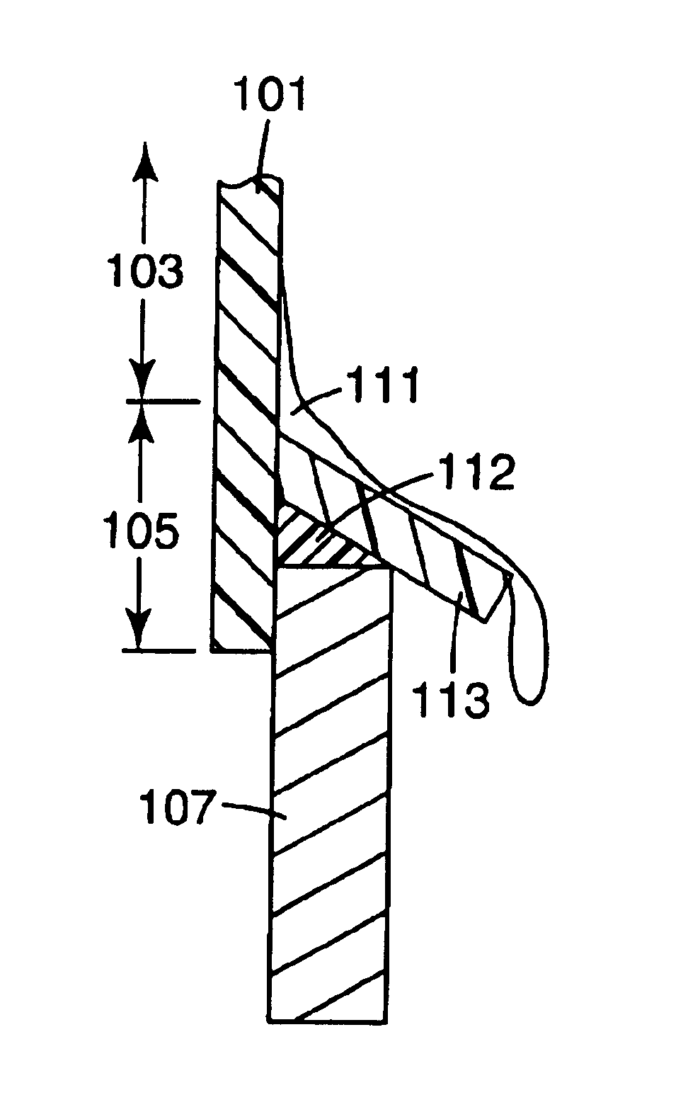
[0012]Briefly described, the present invention is directed at a non-conductive barrier for use in conjunction with a touch screen to prevent streaming liquids from directly or capacitively coupling an active portion of the touch screen with a conductive bezel around the touch screen. The non-conductive barrier is also configured to direct liquids streaming downward from an upper portion of the touch screen outward and away from the active portion of the touch screen.
[0013]FIG. 1 is a cross-sectional cutaway view of a touch screen display 100 including one embodiment of the present invention. Preferably, the touch screen display 100 includes a Near Field Imaging (NFI) capacitive touch screen 101 having an active portion 103 and an inactive portion 105. As discussed above, an electric field is set up on the active portion 103 and a controller (not shown) senses a modulation of the electric field caused by a touch or contact on or near the active portion 103. The inactive portion 105 serves as a buffer between the active portion 103 and a conductive bezel 107 to help prevent the conductive bezel 107 from influencing the electric field and causing capacitive coupling to the touch screen 101. In addition, a gasket may be used between the bezel 107 and the touch screen 101 to further insulate the two.
[0014]As described above, in some environments, conductive liquids (e.g., water) 111 may run down the surface of conventional touch screen displays essentially creating a conductive path from the active portion 103 over the inactive portion 105 and to the conductive bezel 107. However, in accordance with the invention, a non-conductive barrier 113 is used to prevent the conductive liquid 111 from electrically coupling the conductive bezel 107 to the active portion 103 of the touch screen 101. In essence, the non-conductive barrier 113 acts to prevent a single continuous stream of conductive liquid 111 from bridging the gap between the active portion 103 and the conductive bezel 107.
[0015]In the described embodiment, the non-conductive barrier 113 is attached to the touch screen 101 and extends or projects out from or over the bezel 107 a sufficient distance to prevent direct or capacitively-coupled contact between the active portion 103 and the conductive bezel 107. Preferably, the non-conductive barrier 113 is connected to the inactive portion 105 of the touch screen 101 to avoid an unnecessary load on the touch screen 101. Also preferably, to ease the flow of liquids 111 off the touch screen 101, the non-conductive barrier 113 may extend from the touch screen 101 at an obtuse angle so as not to cause streaming liquids to puddle or gather against the touch screen 101. In any event, it is envisioned that the non-conductive barrier 113 is constructed of appropriate design and affixed to the touch screen 101 in such a configuration that the angle between the non-conductive barrier 113 and the vertical plane is sufficient to prevent the streaming liquids 111 from forming an unbroken conductive path between the touch screen 101 and the bezel 107. Although depicted in FIG. 1 extending straight from the touch screen 101, it will be appreciated that many other configurations may work equally as well, such as a curved or otherwise shaped extension. Likewise, an alternative embodiment may include a lip portion (not shown) that more fully encloses the conductive bezel 107. The lip portion could provide more protection against the conductive liquid 111 forming a conductive path between the active portion 103 of the touch screen 101 and the conductive bezel 107.
[0016]The non-conductive barrier 113 may be constructed of any suitable non-conductive material, such as, in one example, 0.125 inch thick plastic. The non-conductive barrier 113 may be bonded to the touch screen 101 with any suitable non-soluble, non-conductive, non-hydroscopic sealing material 112, such as, in one example, RTV silicone.
[0017]FIG. 2 is a frontal view of a non-conductive barrier 213 affixed to an upper portion of a capacitive touch screen 201, in accordance with one embodiment of the present invention. In accordance with this embodiment, the non-conductive barrier 213 is again affixed or bonded to an inactive portion 205 of the touch screen 201 that forms a border between the active portion 203 of the touch screen and a conductive bezel 207. In this embodiment, the non-conductive barrier 213 forms a channel at the upper end that slopes from the middle downward in both directions (220, 221) to cause liquid to drain off to the side before overflowing onto the touch screen. FIG. 2 illustrates how a conductive liquid coming from above the touch screen 201 may be contained by the non-conductive barrier 213 and redirected around the upper portion of the touch screen to drain down along the sides of the touch screen 201. In an alternative embodiment, the upper channel is not sloped and is of sufficient depth that liquids drain off to the sides before overflowing onto the touch screen 201.
[0018]FIG. 3 is a cross-sectional cutaway view of the upper portion of the non-conductive barrier 213 illustrated in FIG. 2 and connected to the upper portion of the touch screen 201. FIG. 3 illustrates how the non-conductive barrier 213 essentially traps conductive liquid 311 that flows down the conductive bezel 207 from above the touch screen 201. The non-conductive barrier 213 accumulates the liquid 311 and redirects the liquid to flow down the sides of the touch screen 201, as illustrated in FIG. 2. In this way, the liquid 311 does not form a conductive path between the conductive bezel 207 and the active portion 203 of the touch screen 201. Again, it should be noted that the non-conductive barrier 213 is attached to the touch screen 201, and a non-conductive sealing material 312 is used to form a bond between the non-conductive barrier 213 and either the touch screen 201, the conductive bezel 207, or both. It should be appreciated that although the invention has been described in terms of embodiments having the non-conductive barrier affixed to the touch screen, the non-conductive barrier could equally be attached to the conductive bezel while serving the same purpose in substantially the same manner.
[0019]FIG. 4 is a perspective view of a touch screen display 400 having a non-conductive barrier 413. An inactive portion of the touch screen 401 forms a border between an active portion 403 of the touch screen 401 and a conductive bezel 407. The non-conductive barrier 413 is attached to the touch screen 401, preferably in the inactive portion 405, and extends out to form a barrier to streaming liquids flowing down the touch screen 401 or the conductive bezel 407. Preferably the non-conductive barrier 413 is continuous and completely borders the bezel opening on all sides. In this way, conductive liquid flowing along one of the four sides of the non-conductive barrier 413 could not make its way between a crack or other discontinuity in the non-conductive barrier 413. Alternatively, some protection could still be gained from a discontinuous barrier placed on a portion of one or more sides of the touch screen 401.
[0020]In summary, a non-conductive barrier is used to prevent liquids from streaming down onto a capacitive touch screen and forming a conductive path between an active portion of the touch screen and a conductive bezel. In this way, many false signals and erroneous touches due to such conductive liquids are avoided.
[0021]The above specification, examples and data provide a complete description of the manufacture and use of the composition of the invention. Since many embodiments of the invention can be made without departing from the spirit and scope of the invention, the invention resides in the claims hereinafter appended.

PUM

no PUM

Description & Claims & Application Information

We can also present the details of the Description, Claims and Application information to help users get a comprehensive understanding of the technical details of the patent, such as background art, summary of invention, brief description of drawings, description of embodiments, and other original content. On the other hand, users can also determine the specific scope of protection of the technology through the list of claims; as well as understand the changes in the life cycle of the technology with the presentation of the patent timeline. Login to view more.
Why Eureka
Try Eureka