Eureka AIR delivers breakthrough ideas for toughest innovation challenges, trusted by R&D personnel around the world.

Holddown device for hardcopy apparatus

a technology of holding device and hardcopy apparatus, which is applied in the direction of printers, thin material processing, instruments, etc., can solve the problems of increased noise, time-consuming and additional manufacturing steps, and increased manufacturing costs, and achieves the effect of light weight and structural rigidity

Inactive Publication Date: 2005-08-09
HEWLETT PACKARD DEV CO LP
View PDF17 Cites 22 Cited by
  • Summary
  • Abstract
  • Description
  • Claims
  • Application Information

AI Technical Summary

Benefits of technology

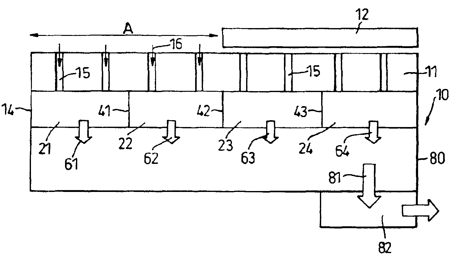
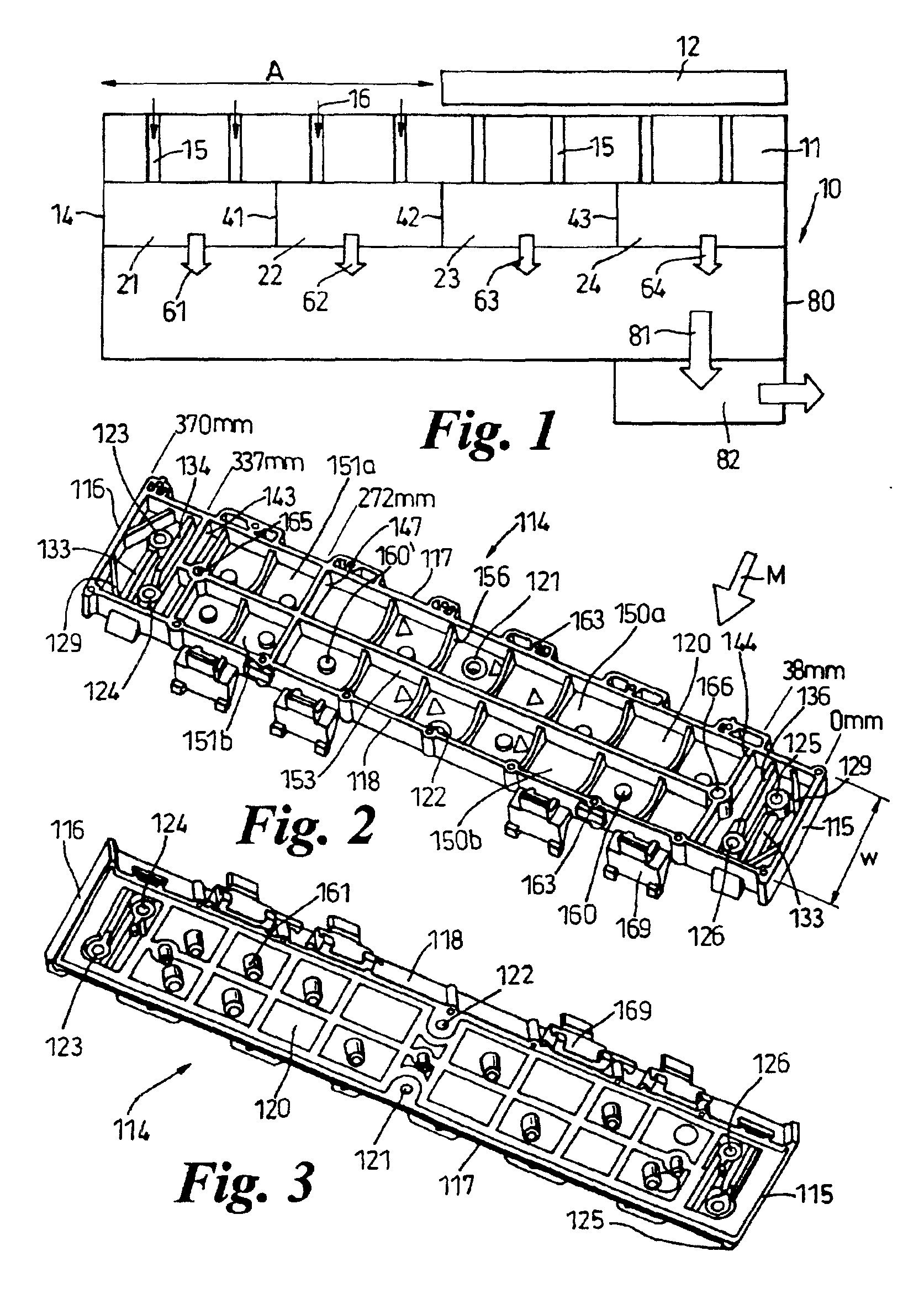
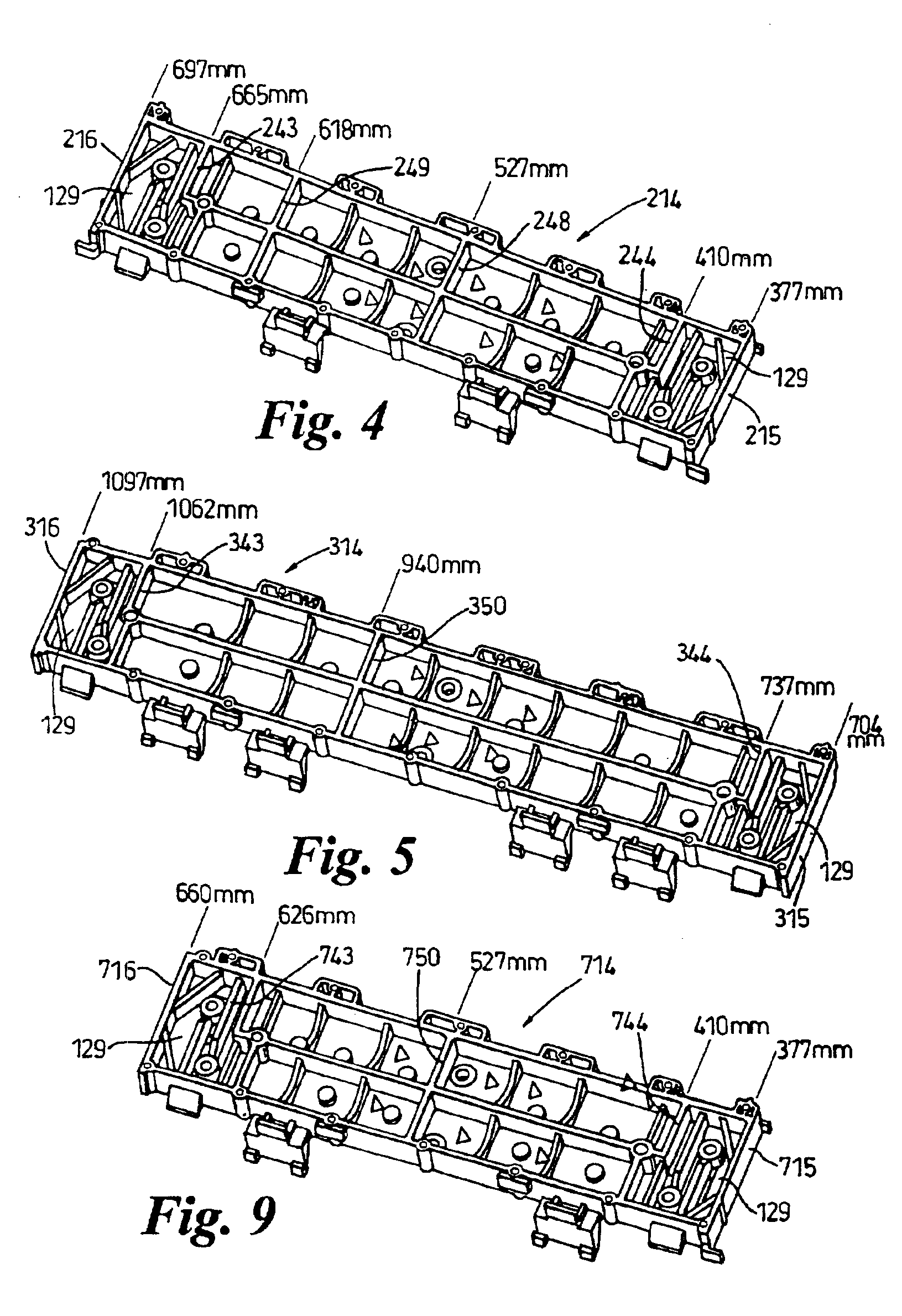
[0007]The first component is preferably molded. This has the advantage that the walls between the chambers and the communication openings between the chambers and the conduit can be produced in the molding process. The first component is conveniently made of a plastics material, which has the advantage of being relatively light in weight.
[0008]The second component is preferably metallic, e.g. of sheet steel material. This has the advantage of giving structural rigidity to the hardcopy apparatus while being relatively inexpensive.
[0013]An advantage of the above arrangement is that a satisfactory negative pressure is applied to the media as soon as its leading edge substantially covers all the holes through the platen which are in communication with the chambers in the first row.
[0015]Preferably, the walls separating the chambers from each other in the first row are aligned with the walls separating the chambers from each other in the second row. Openings are provided between the chambers and a vacuum conduit and in preferred embodiments the arrangement is such that the number and / or size and / or pattern of openings differ between the rows of chambers. This has the advantage that the suction effect on the media can be more precisely controlled as the media arrives at and leaves the platen.
[0028]Although holes are needed in the platen to provide communication with the vacuum chambers underneath, the section or diameter of these holes should be kept as small as possible, but not too small so that can be easily closed by paper wear, debris, dust, ink or the like, in order to decrease the flow of air passing therethrough when no media is covering them. Preferably the cross-section of a hole is comprised between 1 and 3 mm. With a conventional cross-sectional shape, e.g. circular, the airflow is found to produce whistling if the section is too small, e.g. 2.0 mm or less in diameter. Thus the present invention seeks to overcome or reduce the whistling noise and its impact on the user.

Problems solved by technology

These additional manufacturing steps are time-consuming and add expense.
Since such printers have a relatively small number of vacuum chambers, for certain widths of media the pressure applied at the platen tends to be too low.
One solution would be to raise the level of the maximum pressures in order to raise the minimum pressures too, but this requires bigger fans, or more fans, and leads to an increase in noise levels.
A further disadvantage of such printers is lack of uniformity of the pressure applied along the length of the platen.
In fact, having more holes may cause higher losses of pressure when loading smaller media which cannot cover all the holes in fluid communication with one vacuum chamber.

Method used


Image

  • Holddown device for hardcopy apparatus
  • Holddown device for hardcopy apparatus
  • Holddown device for hardcopy apparatus

Examples


Embodiment Construction

[0042]Referring to FIG. 11, a printer 1110 includes a housing 1112 mounted on a stand 1114. The housing has left and right drive mechanism enclosures 1116 and 1118. A control panel 1120 is mounted on the right enclosure 1118. A carriage assembly 1100 illustrated in phantom under a cover 1122, is adapted for reciprocal motion along a carriage bar 1124, also shown in phantom. The carriage assembly 1100 comprises four inkjet printheads 1102, 1104, 1106, 1108 that store ink of different colours, e.g. black, magenta, cyan and yellow ink respectively, and an optical sensor 1105. As the carriage assembly 1100 translates relative to the medium 1130 along the M and Y axis, selected nozzles of the printheads 1102, 1104, 1106, 1108 are activated and ink is applied to the medium 130. The colours from the three colour printheads are mixed to obtain any other particular colour. The position of the carriage assembly 1000 in a horizontal or carriage scan axis (Y) is determined by a carriage positio...


PUM


Abstract

A media holddown device a plastics vacuum guide attached to a sheet metal vacuum beam, the guide includes vacuum chambers in communication with the beam through openings to control the negative pressures applied to media of varying widths by a fan. Dividing walls are provided between the chambers to maintain the value of the negative pressure larger than a predetermined value, especially for media with conventional widths. An intermediate wall divides the guide into front and rear chambers to increase the control of media leading edges. The number, size and pattern of arrangement of openings are selected to produce desired air flow characteristics.

Description

FIELD OF THE INVENTION[0001]The present invention relates to a media holddown device for hardcopy apparatus such as printers, copiers, scanners and facsimile machines. In particular it relates to a suction or vacuum holddown device to maintain a media flat on a platen.BACKGROUND OF THE INVENTION[0002]An example of a previous apparatus comprising such a holddown device is the HP Design Jet 1000 printer, many features of which are disclosed in EP-A-0997308. The holddown device of this printer comprises a platen, a plurality of vacuum chambers for applying a negative pressure to a media positioned on the platen, a vacuum conduit connected to said vacuum chambers, and a vacuum source connected to said vacuum conduit. The vacuum chambers and the vacuum conduit are manufactured from a single piece of extruded aluminium. However, the walls between the vacuum chambers have to be added in a separate manufacturing step. Moreover, holes connecting the vacuum chambers to the vacuum conduit have...

Claims


Application Information

Patent Timeline
IPC IPC(8): B41J11/00B41J11/02B41J13/00
CPCB41J11/0025B41J11/0085B41J11/02
Inventor HINOJOSA, ANTONIOBRUGUE, JOAQUIMJANSA, MARCVALLES, LLUISMAGRANS, FRANCESC XAVIER
Owner HEWLETT PACKARD DEV CO LP
Why Eureka
Eureka Blog
Learn More