Method and arrangement for optical stress analysis of solids

a technology of optical stress analysis and solids, applied in the direction of force measurement by measuring optical property variation, material analysis, instruments, etc., can solve the problems of high phase shift direction, inability to provide directional information about the position of the principal axes of elliptically polarized, and inability to overcome the effect of methods

Active Publication Date: 2005-08-09
PVA METROLOGY & PLASMA SOLUTIONS GMBH
View PDF12 Cites 19 Cited by
  • Summary
  • Abstract
  • Description
  • Claims
  • Application Information

AI Technical Summary

Benefits of technology

[0014]It is the primary object of the invention to find a novel possibility for measurement of stresses in solids based on stress induced birefringence which enables a highly-sensitive quantitative determination of the phase difference

Problems solved by technology

However, the real problem with these methods, known per se, consists in that the quantity to be measured is given by typically extremely small phase shifts (Γ−4) between the ordinary and extraordinary beam.
It will be seen immediately that these methods do not provide directional information about the position of the principal axes of elliptically polarized light and provide exclusively a quadratic dependence of the phase shift.
Due to the quadratic dependence, the sensitivity approaches zero particularly for small phase shifts Γ and statistically equally distributed depolarizations in the material lead to erroneous measurement results in the direction of high values of the phase shift.
However, none of these methods is capable of overcoming the disadvantages resulting from the quadratic dependence, namely, an extremely low measurement sensitivity for small phase shifts and a falsification of the measurement results in the direction of high values brought about by depolarizat

Method used


Image

  • Method and arrangement for optical stress analysis of solids
  • Method and arrangement for optical stress analysis of solids
  • Method and arrangement for optical stress analysis of solids

Examples


Embodiment Construction

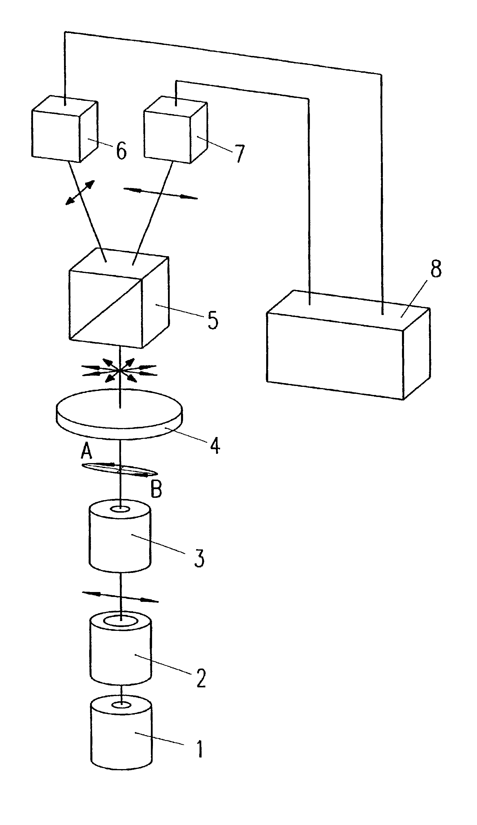
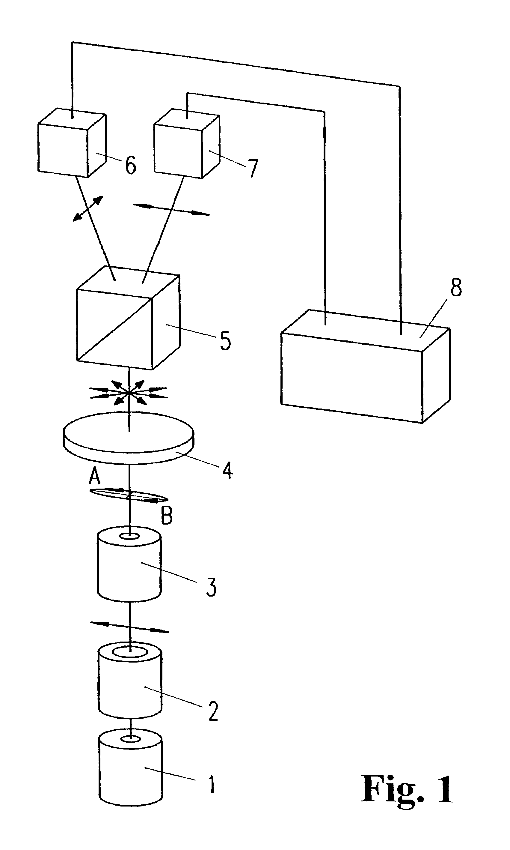
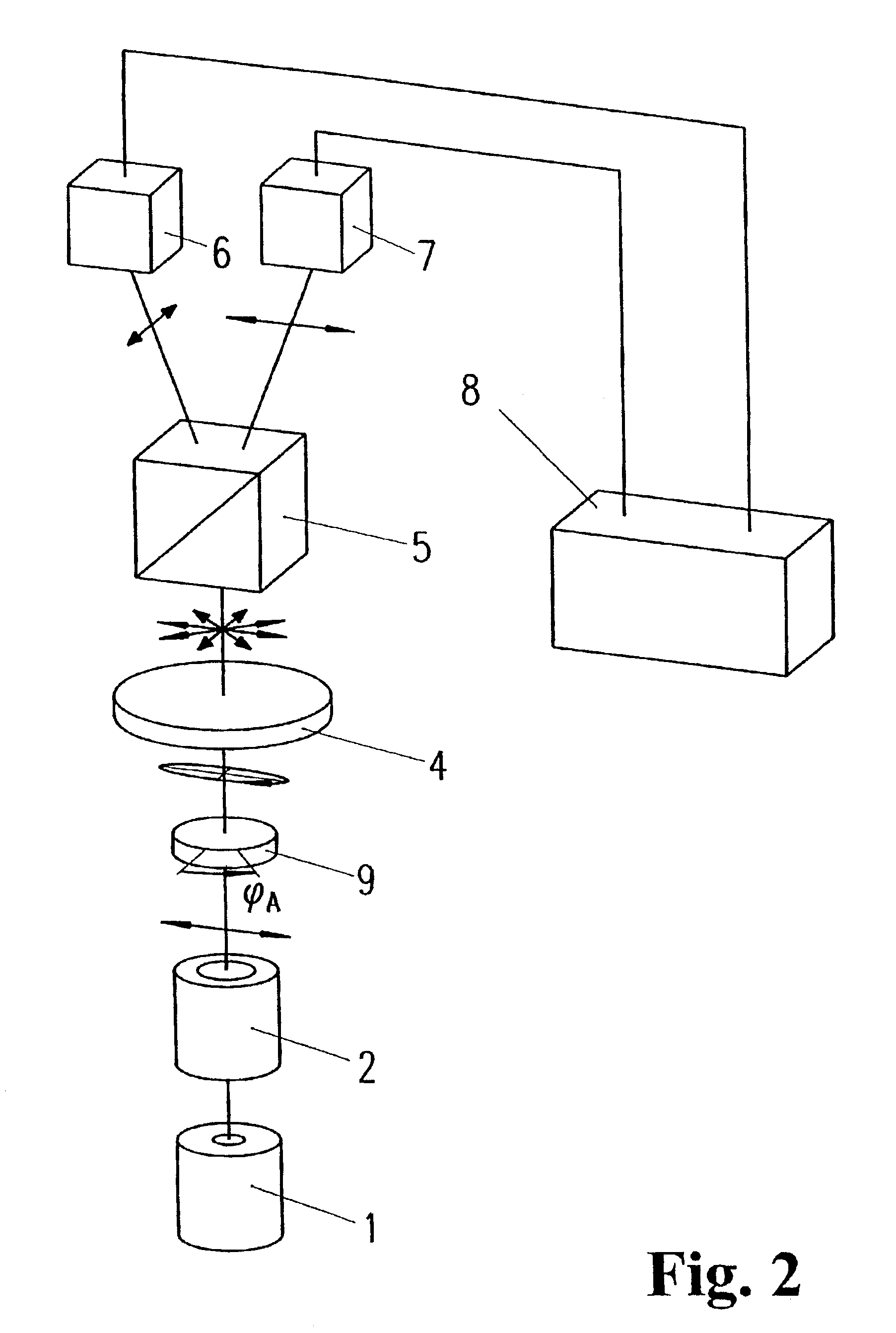
[0050]The method according to the invention and the arrangements based on the method rely on basic constructions of two-channel polarimeters, known per se, using linearly polarized light for analyzing phase shifts (birefringence effects). Known arrangements of this kind comprising, successively, a light source, a linear polarizer, the measurement sample, a polarizing splitter, one of whose two orthogonal polarization directions is oriented at 90° to the linear input polarization, and two light receivers measuring incident light intensities in two orthogonal polarization channels, are expanded, according to the invention, by an optical unit which produces an elliptical polarization of light. The elliptical polarization has the particular feature that the polarization ellipse has a very large ratio of the large principal axis to the small principal axis and, in two measurement phases A and B, a first state of the direction of rotation of the elliptical polarization can be switched to ...


PUM


Abstract

A method for optical stress analysis comprises the steps of directing an incident beam of polarized light to the sample to be analyzed and analyzing a light bundle exiting the sample in two detection channels extending perpendicular to one another with respect to the polarization direction, providing that the incident beam is elliptically polarized, carrying out the elliptical polarization with an elliptic shape having a comparatively large ratio of the large principal axis to the small principal axis, the direction of rotation of the elliptical polarization of the incident beam changing periodically and using two alternative states of the direction of rotation for each measurement process, adjusting the detection channels which extend perpendicular to one another corresponding to the position of the principal axes of the ellipse and carrying out the difference between two measurements consecutively with the same beam intensity of the incident beam and the same ratio of principal axes, but with opposite direction of rotations of the elliptical polarization, being given by the two detection channels. An arrangement in accordance with the method is also disclosed.

Description

CROSS-REFERENCE TO RELATED APPLICATIONS[0001]This application claims priority of German Application No. 101 54 008.6, filed Oct. 28, 2001, the complete disclosure of which is hereby incorporated by reference.BACKGROUND OF THE INVENTION[0002]a) Field of the Invention[0003]The invention is directed to a method and an arrangement for optical stress analysis of solids based on the measurement of the change in the polarization state of light passing through material.[0004]b) Description of the Related Art[0005]In the field of material testing for absence of stress, polarimetric measurement of stress in the test piece by means of a quantity proportional to the shearing stress has proven desirable. However, the real problem with these methods, known per se, consists in that the quantity to be measured is given by typically extremely small phase shifts (Γ<10−4) between the ordinary and extraordinary beam. In this connection, it is self-evident that such small measurement quantities are s...

Claims


Application Information

Patent Timeline
IPC IPC(8): G01L1/24G01N21/21G01N21/23
CPCG01L1/24G01N21/23
Inventor GEILER, HANS-DIETERWAGNER, MATTHIAS
Owner PVA METROLOGY & PLASMA SOLUTIONS GMBH
Why Eureka
Try Eureka