Rotary image viewing apparatus connected to a rotary mirror camera

Inactive Publication Date: 2005-08-09
NEC CORP
View PDF3 Cites 32 Cited by
  • Summary
  • Abstract
  • Description
  • Claims
  • Application Information

AI Technical Summary

Benefits of technology

[0033]The present invention has been worked out in view of the problems in the prior art set forth above. It is therefore an object of the present invention to

Problems solved by technology

Accordingly, for observing the object from the position distanced in horizontal direction instead of directly above the user, a complicated optical system is required and is significantly difficult or even impossible to realize in certain case.
The camera and monitor are relatively bulky and heavy.
Accordingly, both of the rotatable universal head type

Method used


Image

  • Rotary image viewing apparatus connected to a rotary mirror camera
  • Rotary image viewing apparatus connected to a rotary mirror camera
  • Rotary image viewing apparatus connected to a rotary mirror camera

Examples


first embodiment

[External Appearance]

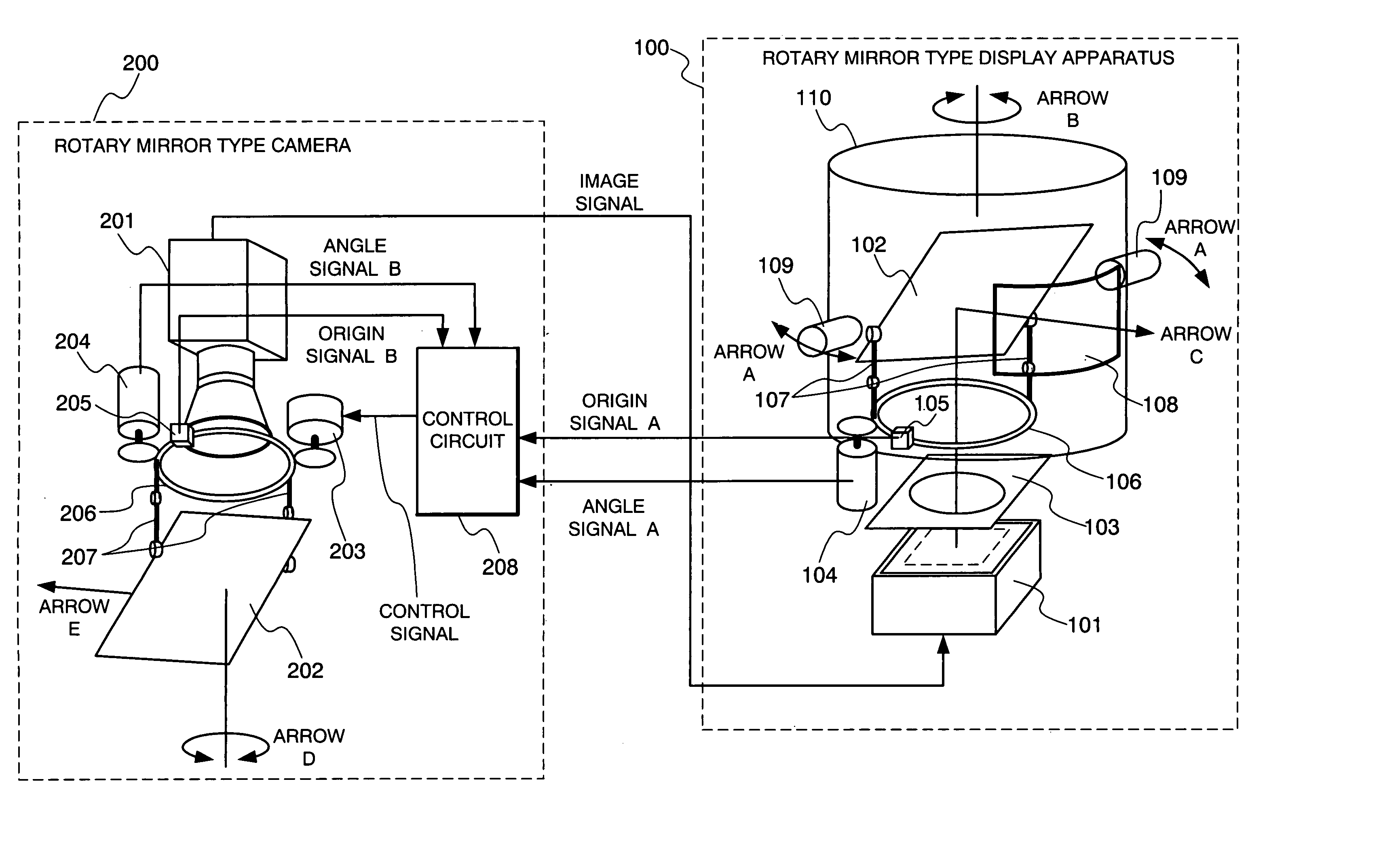
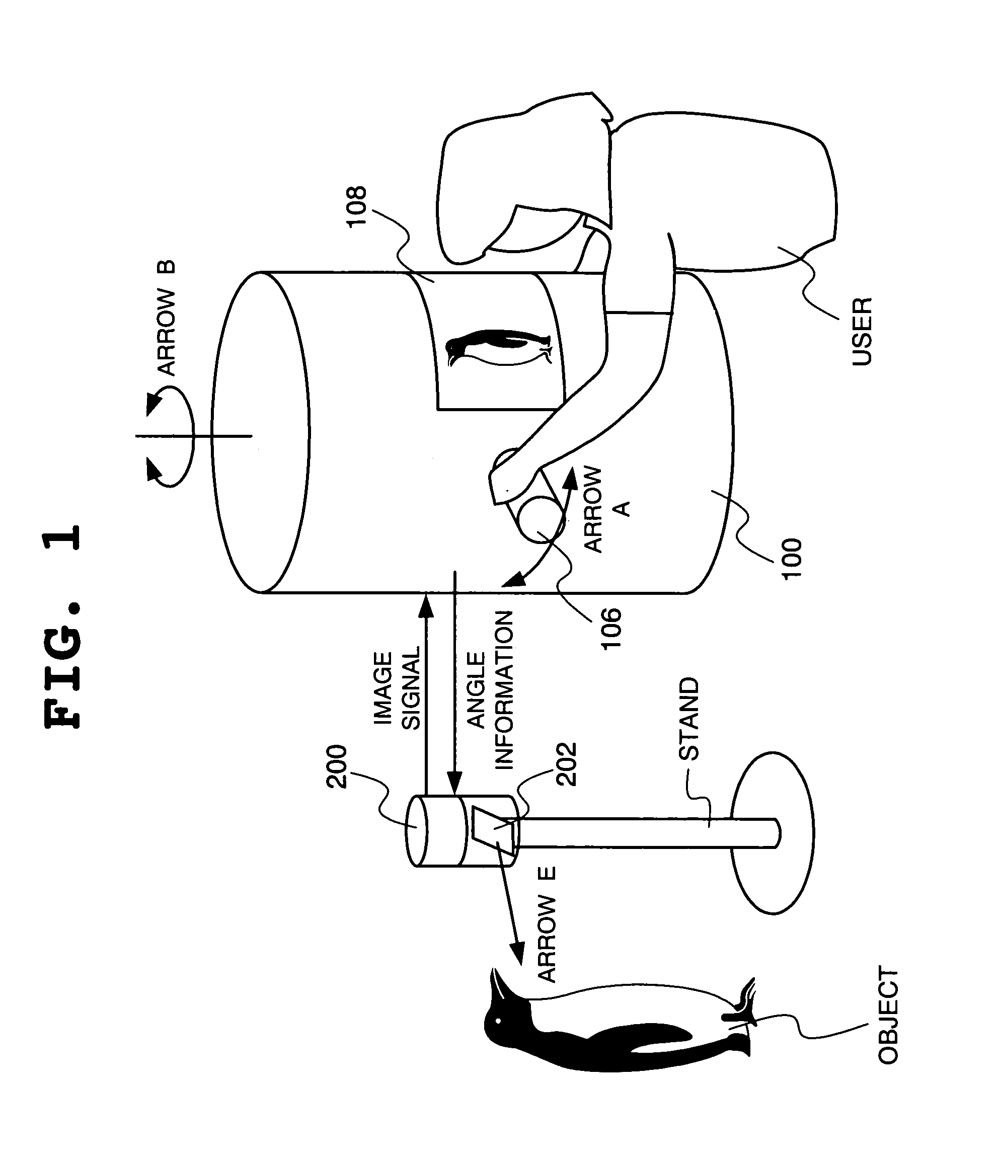
[0125]FIG. 1 is an illustration showing an external view of the first embodiment of a camera system according to the present invention.

[0126]Referring to FIG. 1, the first embodiment of a camera system according to the present invention is constructed with a rotary mirror type display apparatus 100 and a rotary mirror type camera 200.

[0127]A user grips a handle 106 with observing an image picked-up by the rotary mirror type camera 200 looking into a finder 108. The user rotates the rotary mirror type display apparatus 100 as shown by arrow B. Then user may observe or view the surrounding of the rotary mirror type camera 200.

[0128]If a cable between the rotary mirror type display apparatus 100 and the rotary mirror type camera 200 for transferring an image signal and an angle signal is made long or by using radio signal, a condition around the rotary mirror type camera 200 located at remote site can be observed or viewed by the rotary mirror type display apparatu...

second embodiment

[Construction]

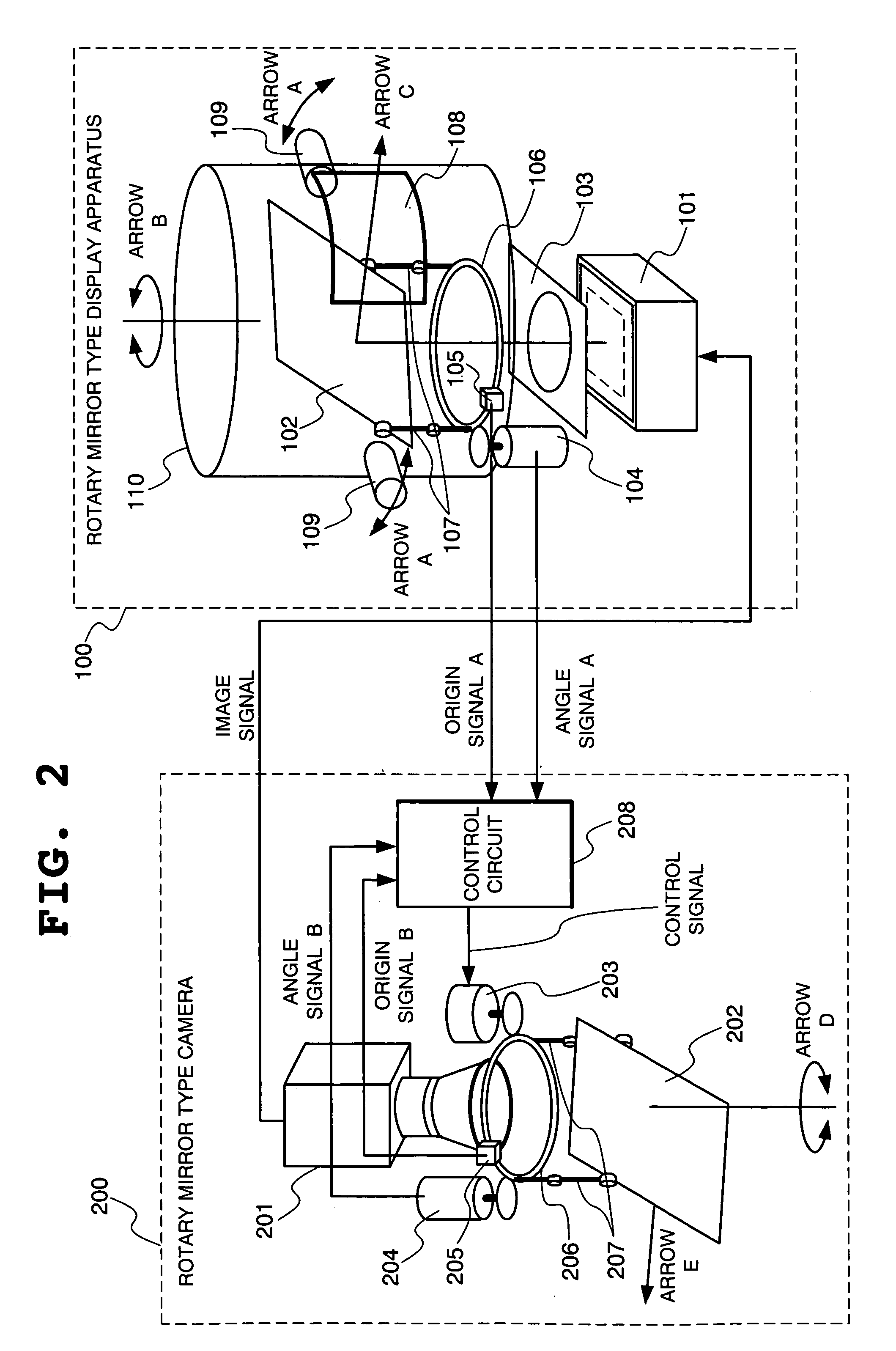
[0158]FIG. 12 is an illustration showing a construction of the second embodiment of the camera system according to the present invention.

[0159]Comparing the shown embodiment and the first embodiment with making reference to FIGS. 12 and 2, there are two differences. First difference is that a rectangular window 103S is employed in the second embodiment in place of the circular window 103 employed in the first embodiment. Another difference is that while the circular window 103 is filed on the side of the monitor 101 (namely, the circular window 103 is separated from the casing 110) in the first embodiment, the rectangular window 103S is integral with the ring gear 106, namely fixed on the side of the casing 110 (since the ring gear 106 is fixed to the casing 110 similarly to the first embodiment). Other constructions are identical to the foregoing first embodiment.

[0160]FIG. 13 is an illustration showing the second embodiment of the rotary mirror type display apparatus...

third embodiment

[Construction, Operation]

[0164]FIG. 16 is an illustration showing a construction of the third embodiment of the camera system according to the present invention.

[0165]Referring to FIG. 16, the shown embodiment of the camera system is constructed with the rotary mirror type display apparatus 100A, in which image conversion means 111A is added to the rotary mirror type display apparatus 100 in the first embodiment, and the rotary mirror type camera 200. Comparing the shown embodiment and the first embodiment with reference to FIGS. 16 and 2, there are two differences. The first difference is that orientation of the camera 201 in the rotary mirror type camera 200 in the first embodiment is vertically downward, and in the shown embodiment, the orientation of the camera 201 is vertically upward. Another difference is that the image conversion means 111A is added to the rotary mirror type display apparatus 100.

[0166]In the shown embodiment and the first embodiment, the construction other ...


PUM


Abstract

A camera system has a rotary mirror type camera assembly including a camera, a mirror for camera arranged in front of the camera, and a mirror rotating mechanism driving the mirror for the camera, a rotary mirror type display apparatus including a monitor displaying an image picked up by the camera, a mirror for monitor arranged in front of the monitor, a finder permitting viewing of the image displayed on the monitor via the mirror for monitor, and a casing rotatable together with the mirror for monitor. The mirror for camera is rotated according to rotation of the casing and the mirror for monitor being fixed to the casing. When the casing is rotated, the mirror for monitor is rotated in display direction of the monitor in front of the monitor.

Description

BACKGROUND OF THE INVENTION[0001]1. Field of the Invention[0002]The present invention relates to a camera system using a rotary mirror type display apparatus which displays an image via a rotary mirror arranged in front of a monitor, and a display apparatus.[0003]2. Description of the Related Art[0004]The present invention concerns a camera system and a display apparatus, in which a rotary camera type display apparatus displaying an image through a rotary mirror arranged in front of a monitor capable of displaying an image from a camera and a rotary mirror type camera picking-up an image of an object via a rotary mirror arranged in front of the camera. In the following disclosure, as discussion for the prior art, to which the present invention is related, examples of two optical and electronic periscopes, one rotary mirror type camera, and one periscope type display apparatus will be discussed.[Optical Periscope][0005]An optical periscope is a periscope operated optically without us...

Claims


Application Information

Patent Timeline
IPC IPC(8): G02B23/08G02B23/02G03B15/00G03B17/00G03B17/56G03B21/28H04N7/00H04N7/18H04N5/232H04N5/225
CPCH04N5/2259H04N5/23203H04N23/58H04N23/66
Inventor KASHITANI, ATSUSHINAKAO, TOSHIYASU
Owner NEC CORP
Why Eureka
Try Eureka