Active antenna system with fault detection

a fault detection and active antenna technology, applied in the field of active antenna power interface, can solve problems such as open circuits, damage to radio receivers, and damage to antenna signal lines, and achieve the effect of preserving the ability of components

Inactive Publication Date: 2005-08-09
VISTEON GLOBAL TECH INC
View PDF12 Cites 41 Cited by
  • Summary
  • Abstract
  • Description
  • Claims
  • Application Information

AI Technical Summary

Benefits of technology

[0009]The present invention has the advantage of providing power to an active antenna while detecting both open-circuit faults and short-circuit faults. Small component sizes are used while preserving the ability of the components to survive a short-circuit condition.

Problems solved by technology

In a mobile receiver system, such as an automotive radio receiver, it may be undesirable to provide an independent power supply having a main power feed at the antenna location.
If bent at too sharp an angle, a break may occur in the antenna signal line.
Some body parts may be assembled after the antenna cable is put in place and the cable may be inadvertently pinched or otherwise damaged during assembly, which can lead to either open circuits (e.g., a break in the signal line) or a short circuit from the signal line to the vehicle body or between the signal line and the ground line (e.g., the shield conductor or a coaxial cable).
In the event of a short-circuit, the potential exists for damage to the radio receiver.
However, smaller sized components are more likely to be destroyed during a short-circuit condition.

Method used


Image

  • Active antenna system with fault detection
  • Active antenna system with fault detection
  • Active antenna system with fault detection

Examples


Embodiment Construction

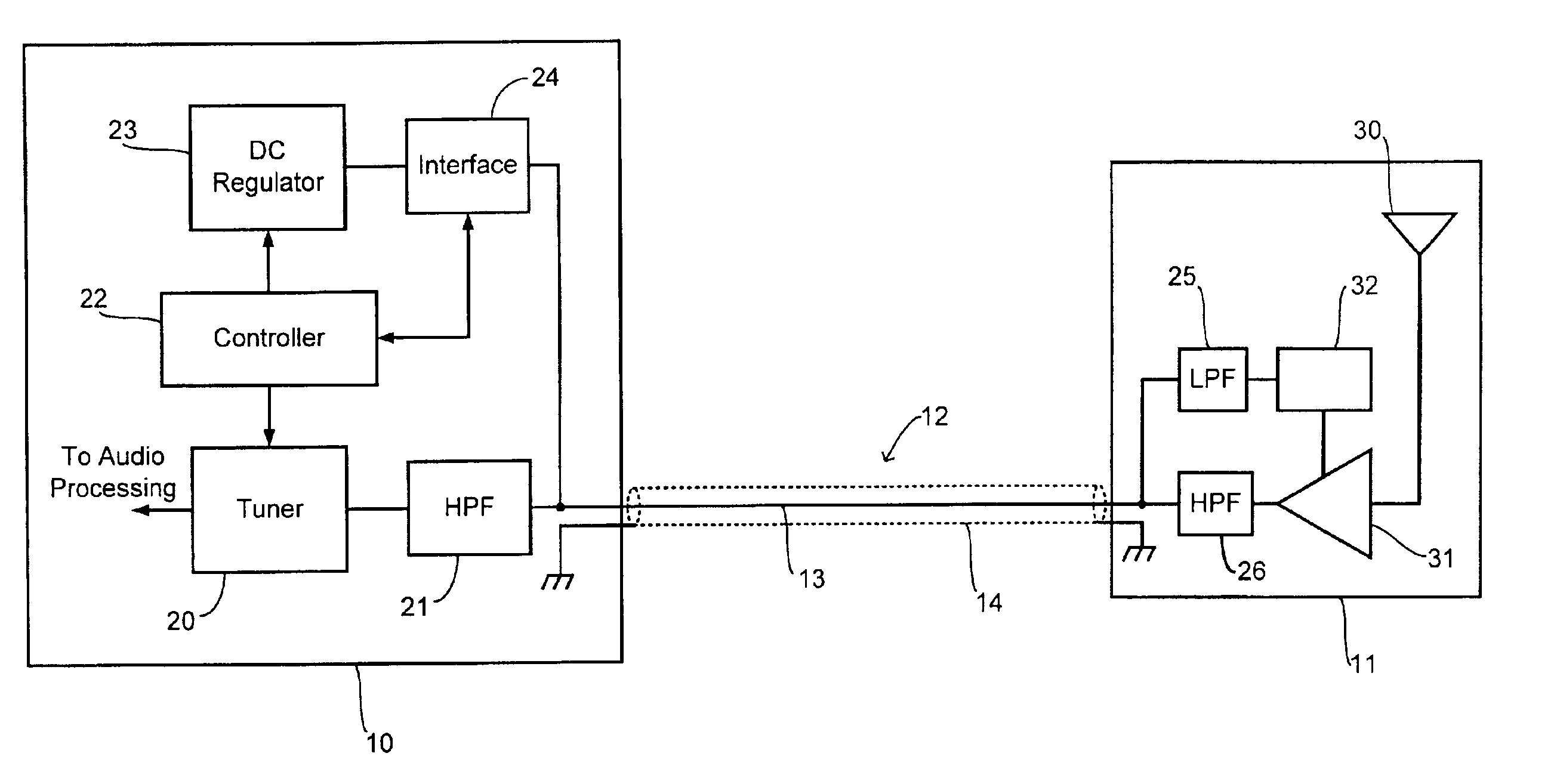
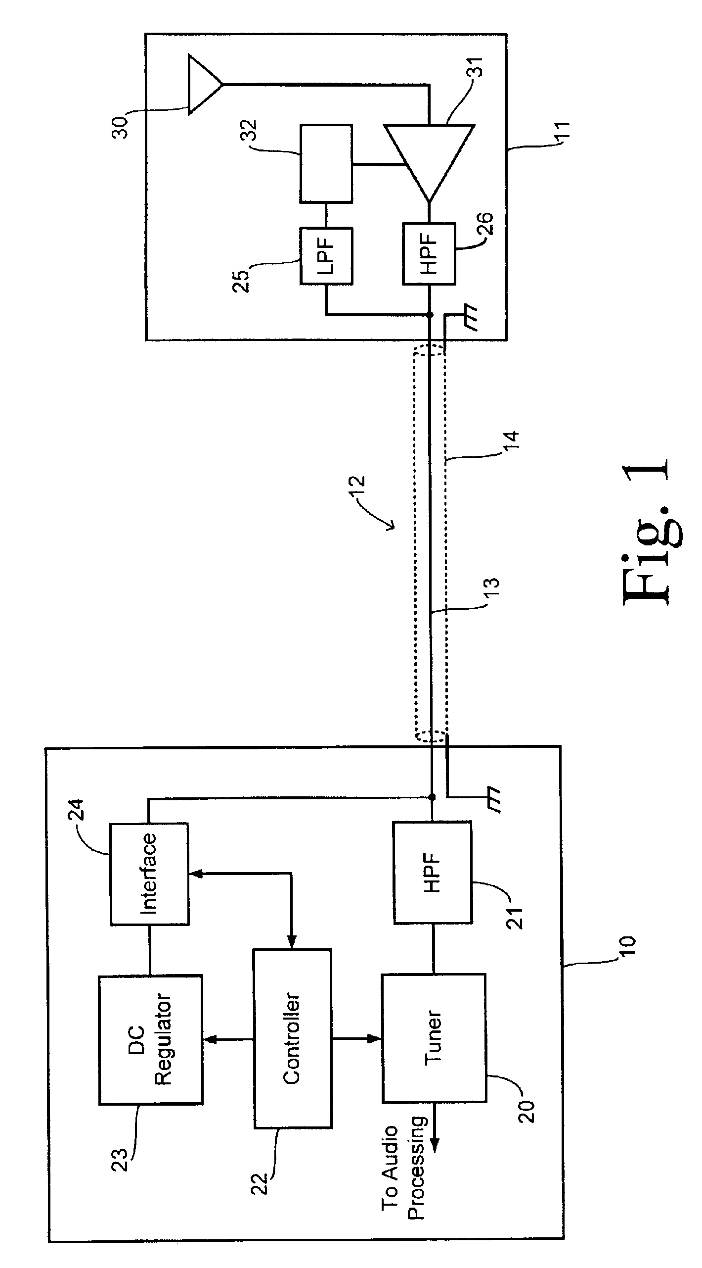
[0014]Referring to FIG. 1, a radio receiver 10 is coupled to a remote antenna module 11 by an antenna feed or cable 12. In the preferred embodiment, antenna cable 12 comprises a coaxial cable having a signal line 13 surrounded coaxially by a grounded shield conductor 14, but other types of transmission lines either carrying both antenna signals and a power supply voltage or used with a separate power conductor can be used. While the preferred embodiment may include an automotive audio system incorporating an S-DARS receiver coupled to a body-mounted antenna module, other types of wireless RF receivers and types of antennas may be employed with the present invention.

[0015]Radio receiver 10 includes an RF tuner 20 that receives RF antenna signals from antenna signal line 13 via a highpass filter (HPF) 21. Demodulated signals from tuner 20 are provided to audio processing circuitry (not shown) such as a digital or analog signal processor. A controller 22 is connected to tuner 20 and to...


PUM


Abstract

An active antenna power interface circuit couples a supply voltage from a radio receiver to an antenna feed. The circuit comprises a DC power input and a power switching element connected in series between the DC power input and the antenna feed. The power switching element has a control input for selecting a conducting state or a nonconducting state of the power switching element. A high side voltage sensor senses a first voltage proportional to a voltage at the DC power input. A low side voltage sensor senses a second voltage proportional to a voltage at the antenna feed. A controller is coupled to the control input and to the voltage sensors. The controller places the power switching element into the conducting state, samples the first and second voltages, calculates a voltage difference in response to the first and second voltages, compares the voltage difference to an upper limit and a lower limit. If the voltage difference is greater than the upper limit then the controller signals a short-circuit fault. If the voltage difference is less than the lower limit then the controller signals an open-circuit fault.

Description

CROSS REFERENCE TO RELATED APPLICATIONS[0001]Not Applicable.STATEMENT REGARDING FEDERALLY SPONSORED RESEARCH[0002]Not Applicable.BACKGROUND OF THE INVENTION[0003]The present invention relates in general to active antenna systems for radio receivers, and, more specifically, to a power interface for an active antenna including fault diagnostics and protection.[0004]Powered antenna systems for radio receivers are often used in order to boost an antenna signal from an external antenna (i.e., an antenna not integrated into the receiver). A powered amplifier is located remotely with the antenna element and the amplified antenna signal is coupled to the receiver via an antenna feed, such as a coaxial cable. The amplification of the antenna signal avoids excessive signal degradation and loss that would occur during transmission from the antenna to the receiver.[0005]In a mobile receiver system, such as an automotive radio receiver, it may be undesirable to provide an independent power suppl...

Claims


Application Information

Patent Timeline
Patent Type & Authority Patents(United States)
IPC IPC(8): H01Q23/00H04B1/18H04B1/04
CPCH01Q23/00H04B1/18H04B1/0466
Inventor WARD, DENNIS PAULZEROD, RICHARD DAVID
Owner VISTEON GLOBAL TECH INC
Why Eureka
Try Eureka