
Mechanism for facilitating backtracking

a technology of backtracking and mechanism, applied in the field of computer systems, can solve the problems of not being able to determine the part of the transformation document that gave rise to the undesired, users often make mistakes in creating the transformation document, etc., and achieve the effect of facilitating backtracking, easy determination, and easy determination

Inactive Publication Date: 2005-08-09
ORACLE INT CORP
View PDF20 Cites 22 Cited by
  • Summary
  • Abstract
  • Description
  • Claims
  • Application Information

AI Technical Summary

Benefits of technology

[0007]In accordance with one embodiment of the present invention, there is provided a mechanism for facilitating backtracking. As used herein, the term backtracking refers to the ability to determine, after processing is performed, what gave rise to a particular result. For example, in a system with backtracking capability, a user can select a particular portion of a result document, and the system will indicate to the user the particular portions of the source and transformation documents that gave rise to that portion of the result document. With the ability to backtrack, a user can easily determine what caused each portion of the result to be generated. By knowing what caused each portion of the result to be generated, the user can more easily determine what needs to be changed to correct an incorrect result. As a result, backtracking greatly aids in the debugging process.

Problems solved by technology

This is often not the case, however.
Because XSLT is a fairly complex language, users often make mistakes in creating the transformation document.
This in turn leads to undesired results in the result document.
Given only the result document, the source document, and the transformation document, it is very difficult if not almost impossible for a user to determine what part of the transformation document gave rise to the undesired results.
As a result, the user does not know what portion or portions of the transformation document to change to correct the problem.
As this discussion shows, it is currently very difficult to debug a transformation document.

Method used

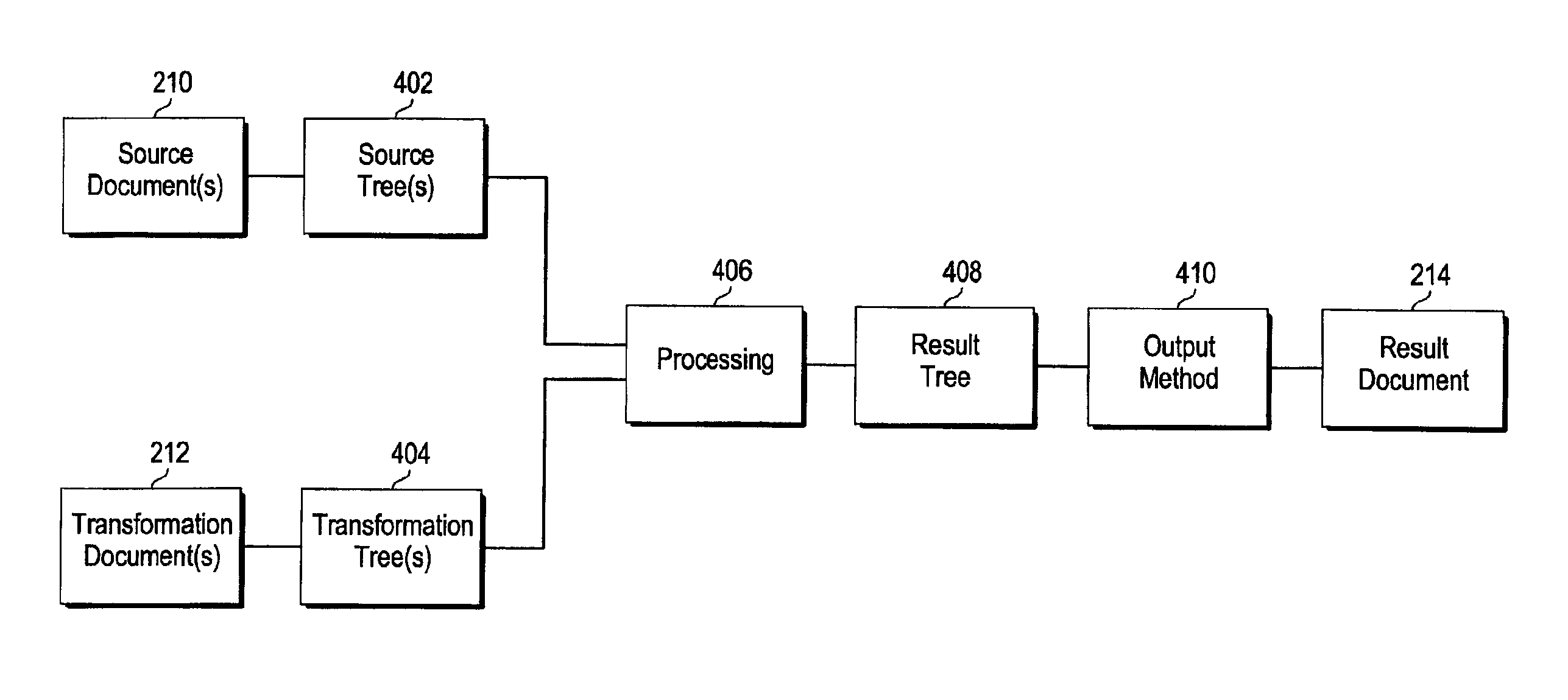

Image

  • Mechanism for facilitating backtracking
  • Mechanism for facilitating backtracking
  • Mechanism for facilitating backtracking

Examples


Embodiment Construction

)

Overview

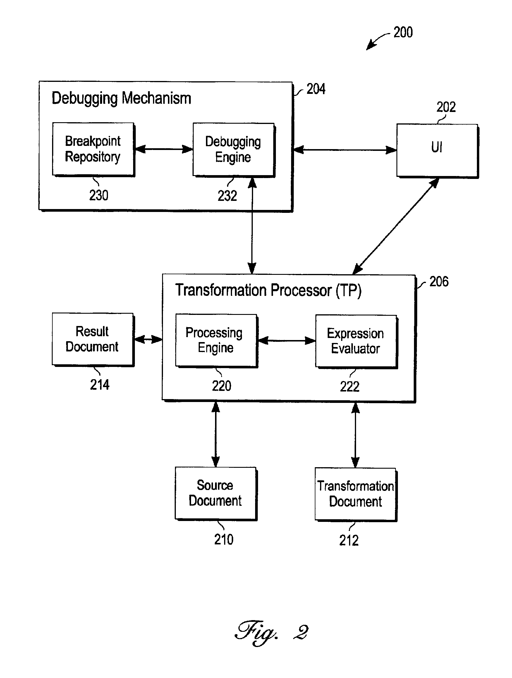
[0015]With reference to FIG. 2, there is shown a functional block diagram of a system 200 in which one embodiment of the present invention may be implemented. As shown, system 200 comprises a user interface (UI) 202, a debugging mechanism 204, and a transformation processor (TP) 206. Together, the various components 202, 204, 206 cooperate to enable a user to carry out various actions, such as setting breakpoints, initiating processing of a source document 210 and a transformation document 212 to derive a result document 214, and viewing intermediate processing results. System 200 makes it simple and convenient for a user to perform transformations and to debug the transformation process. In the following discussion, for illustrative purposes, the present invention will be described in the context of a document transformation process wherein an XML source document 210 is processed with an XSLT transformation document 212 to derive a result document 214. It should be noted, ...


PUM


Abstract

In processing a source entity with a transformation entity, an action set forth in a portion of the transformation entity is executed. A portion of the source entity is the subject of this action. This action causes a particular portion of a result entity to be generated. After this portion of the result entity is generated, a set of history information is associated therewith, which comprises a reference to the portion of the transformation entity that gave rise to the action, and a reference to the portion of the source entity that was the subject of the action. Given this information, it is possible to perform backtracking at a later time, so that when this particular portion of the result entity is selected, those portions of the transformation and source entities that gave rise to the particular portion of the result entity can be indicated to a user.

Description

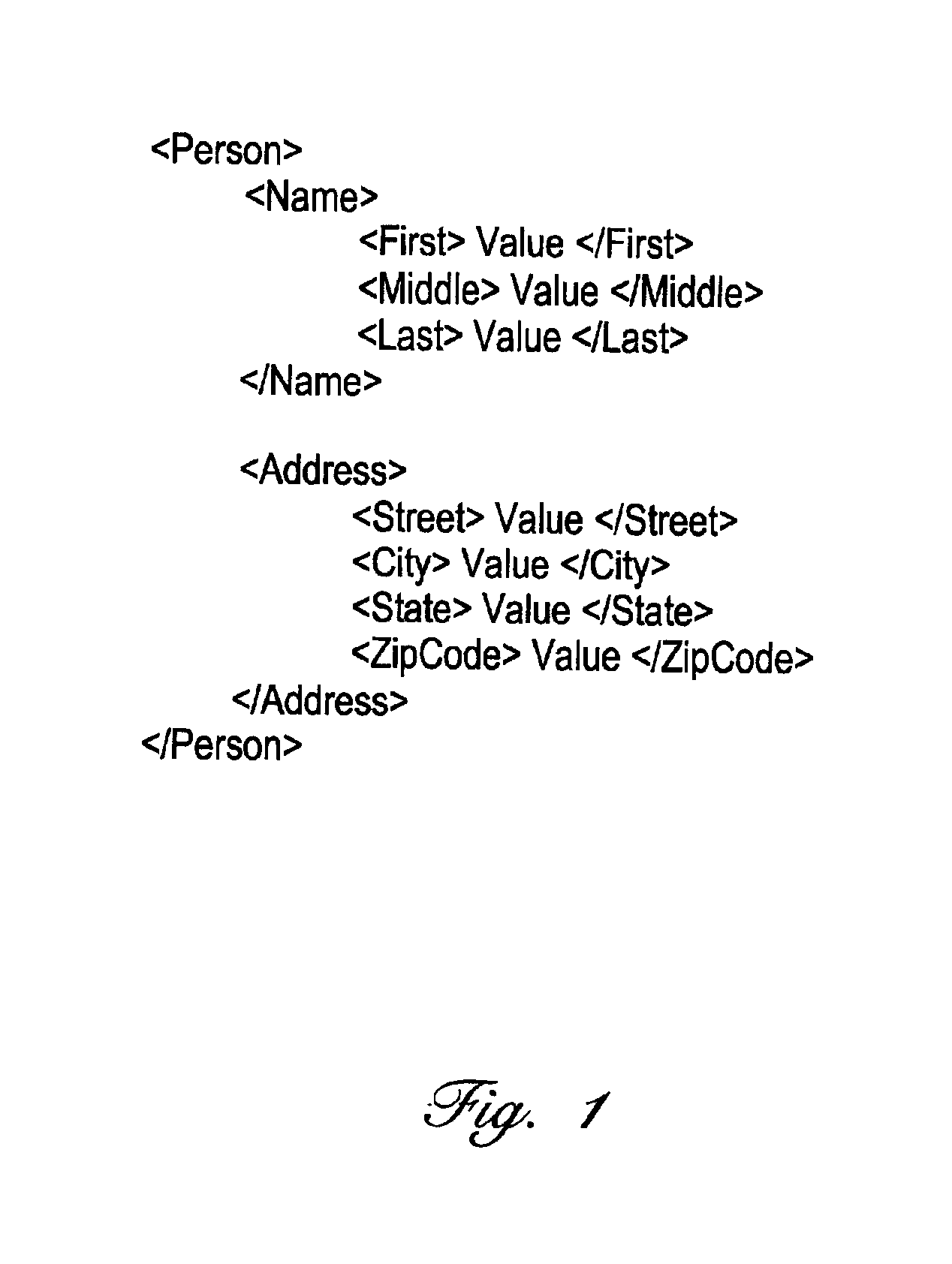
FIELD OF THE INVENTION[0001]This invention relates generally to computer systems, and more particularly to a mechanism for facilitating backtracking.BACKGROUND[0002]The XML (extensible Markup Language) specification established by the W3C Organization provides a standardized methodology for exchanging structured data between different mechanisms. The different mechanisms may be different components within the same system (e.g. different program components) or they may be completely separate systems (e.g. systems of different companies, or different servers on the Internet). Basically, XML allows structured data to be exchanged in a textual format using “element tags” to specify structure and to delimit different sets of data.[0003]An example of a portion of an XML document is shown in FIG. 1. In this example, information about a person is being exchanged. To indicate that the information pertains to a person, the “person” element tags are used to delimit the data. Nested within the ...

Claims


Application Information

Patent Timeline
Patent Type & Authority Patents(United States)
IPC IPC(8): G06F11/36
CPCG06F11/3636Y10S707/99943
Inventor TEN-HOVE, RONALD A.BIRDER, MATTHEW D.
Owner ORACLE INT CORP
Learn More