Integrated gyroscope of semiconductor material with at least one sensitive axis in the sensor plane

a gyroscope and sensor plane technology, applied in the direction of acceleration measurement using interia force, turn-sensitive devices, instruments, etc., can solve the problems of high fabrication cost, low reliability, and drawbacks of above-gyroscopes

Inactive Publication Date: 2005-08-16
STMICROELECTRONICS SRL
View PDF19 Cites 71 Cited by
  • Summary
  • Abstract
  • Description
  • Claims
  • Application Information

AI Technical Summary

Problems solved by technology

However, the above gyroscopes present some drawbacks.
This known gyroscope involves a complicated fabrication process, which uses two different structural layers, with consequent high fabrication costs, low reliability, complication of alignment between the accelerometers and the oscillating masses, and complication in the connections.
However, in case of the gyroscope of circular shape (described in the patent U.S. Pat. No. 5,955,668), the structure is sensitive to stresses due to the fabrication steps and to thermal drift, since the suspension springs of the sensing element internal to the oscillating external mass are very rigid in the direction of the axis of the angular velocity, and it is not possible to an

Method used


Image

  • Integrated gyroscope of semiconductor material with at least one sensitive axis in the sensor plane
  • Integrated gyroscope of semiconductor material with at least one sensitive axis in the sensor plane
  • Integrated gyroscope of semiconductor material with at least one sensitive axis in the sensor plane

Examples


first embodiment

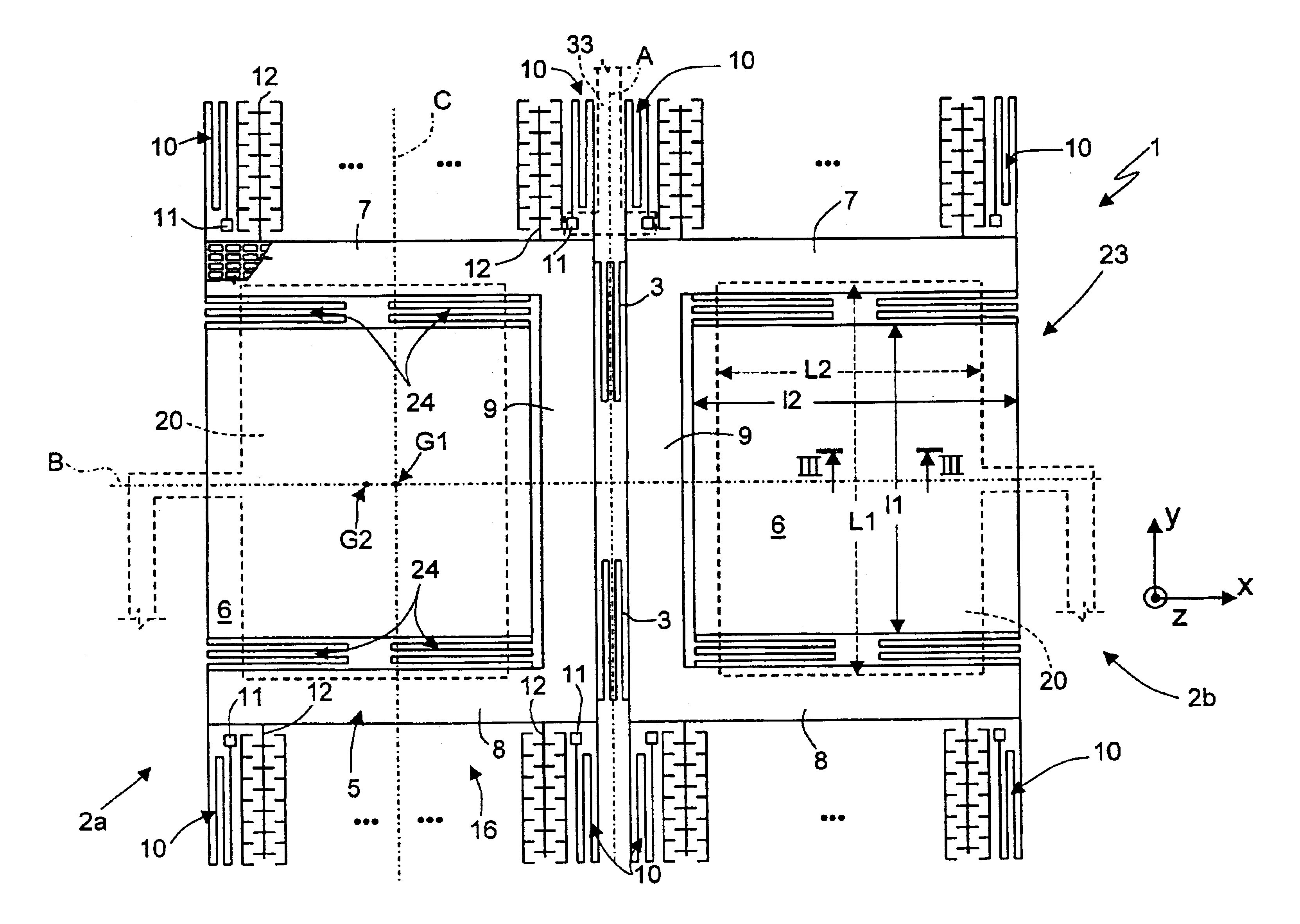
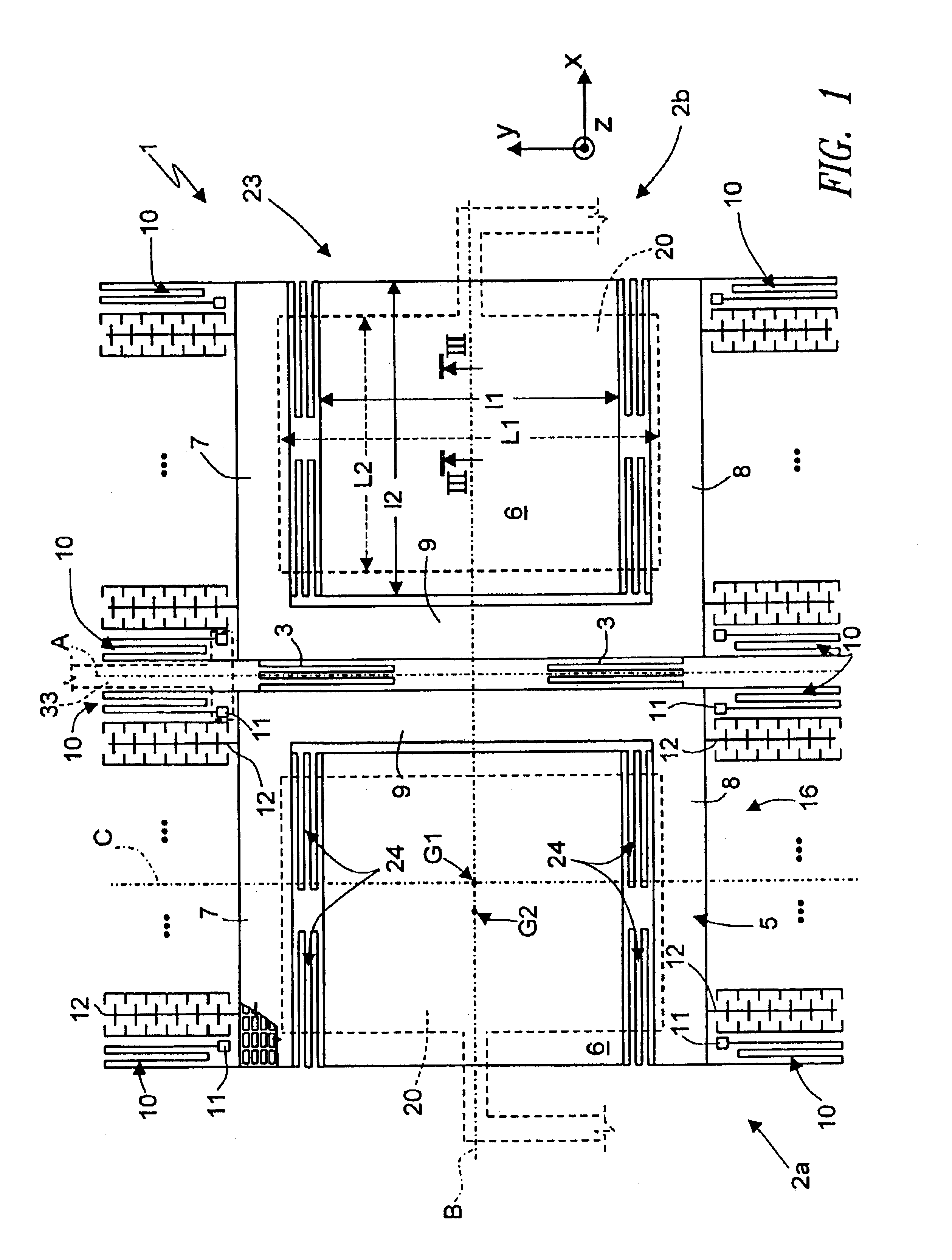
[0025]FIGS. 1 to 3 illustrate a gyroscope 1 according to the invention. As shown in detail in FIG. 1, the gyroscope 1 comprises an acceleration sensor 23 formed by two parts 2a, 2b, which are symmetrical with respect to a central axis of symmetry designated by A and connected together by two central springs 3, configured to be symmetrical with respect to a horizontal centroidal axis designated by B. Furthermore, each part 2a, 2b has a vertical centroidal axis designated by C. The axes A and C are parallel to the axis Y, while the axis B is parallel to the axis X. The intersection between the horizontal centroidal axis B and the vertical centroidal axis C constitutes the centroid G1 of each part 2a, 2b.

[0026]The acceleration sensor 23 is sensitive to an angular velocity directed parallel to the axis Y.

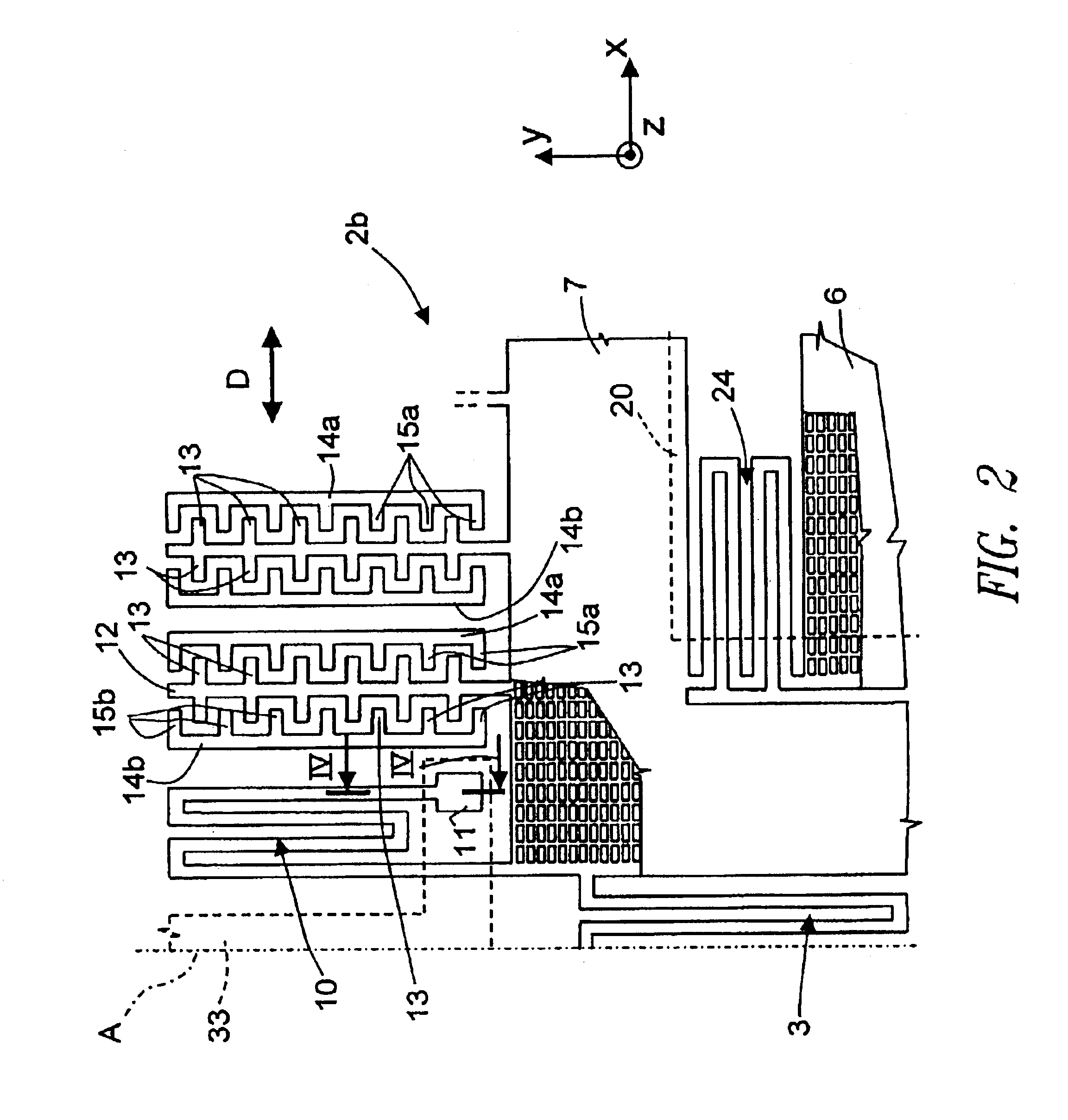
[0027]Each part 2a, 2b comprises a driving element 5 of concave shape, here a square C shape, and a sensitive mass 6, completely housed inside the space delimited by the driving elemen...

third embodiment

[0063]The advantages of the described gyroscope are the following. First, it is possible to have, on a single plane, the sensitive elements that are able to detect forces acting along three Cartesian axes, this enabling a reduction in the overall dimensions of a three-axes gyroscope. The advantage is all the greater in case of the third embodiment, where a single sensor 23 is able to measure forces acting in two perpendicular directions, and hence only two sensors are necessary for a three-dimension measure. The compactness of the sensors and the reduction in their number further enable reduction in costs for manufacturing the gyroscope.

[0064]Each sensor 23 and each sensing set is moreover sensitive only to the forces acting in the respective directions, and rejects actions in a perpendicular direction. Thus a high sensing precision is achieved. The sensing precision may be increased even further by designing the thicknesses of the various layers so as to assign different degrees of...


PUM


Abstract

An integrated gyroscope, including an acceleration sensor formed by: a driving assembly; a sensitive mass extending in at least one first and second directions and being moved by the driving assembly in the first direction; and by a capacitive sensing electrode, facing the sensitive mass. The acceleration sensor has an rotation axis parallel to the second direction, and the sensitive mass is sensitive to forces acting in a third direction perpendicular to the other directions. The capacitive sensing electrode is formed by a conductive material region extending underneath the sensitive mass and spaced therefrom by an air gap.

Description

CROSS-REFERENCE TO RELATED APPLICATION[0001]This application is a continuation-in-part of U.S. patent application Ser. No. 10 / 128,133, filed Apr. 23, 2002, now U.S. Pat. No. 6,766,689, which application is incorporated herein by reference in its entirety.BACKGROUND OF THE INVENTION[0002]1. Field of the Invention[0003]The present invention relates to an integrated gyroscope of semiconductor material.[0004]2. Description of the Related Art[0005]As is known, integrated gyroscopes of semiconductor material, manufactured using MEMS (Micro-Electro-Mechanical Systems) technology, operate on the basis of the theorem of relative accelerations, exploiting Coriolis acceleration. In particular, when a linear velocity is applied to a movable mass rotating with angular velocity, the movable mass “feels” an apparent force, called Coriolis force, which determines a displacement thereof in a direction perpendicular to the linear velocity and to the axis of rotation. The apparent force can be hence d...

Claims


Application Information

Patent Timeline
IPC IPC(8): G01C19/56G01C19/5719
CPCG01C19/5719
Inventor DURANTE, GUIDO SPINOLAZERBINI, SARAHMERASSI, ANGELO
Owner STMICROELECTRONICS SRL
Why Eureka
Try Eureka