

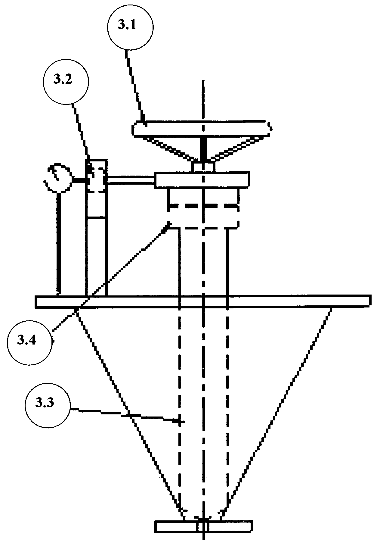
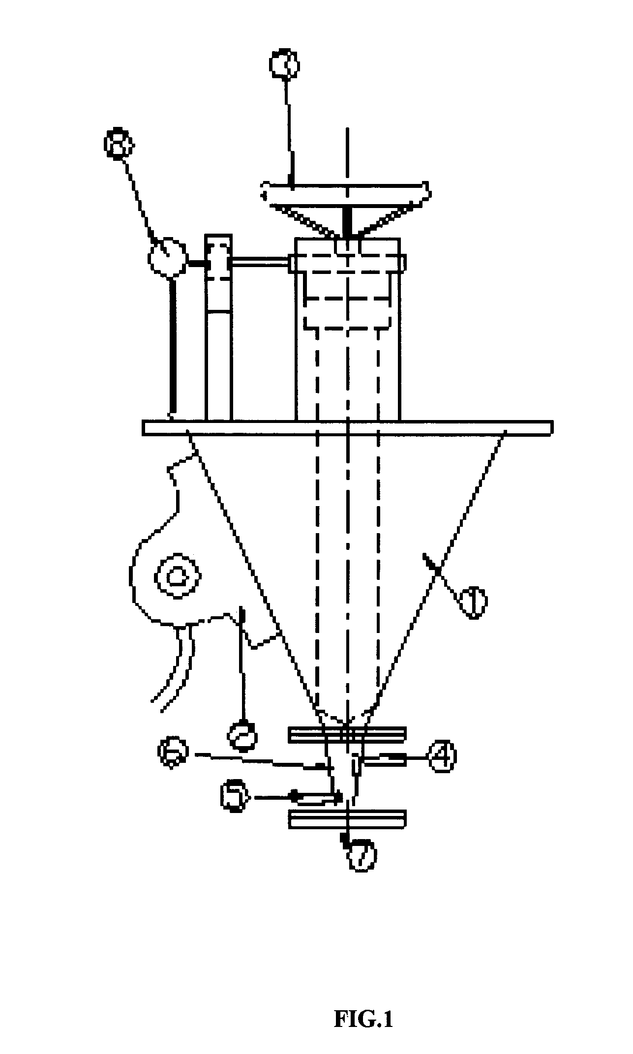
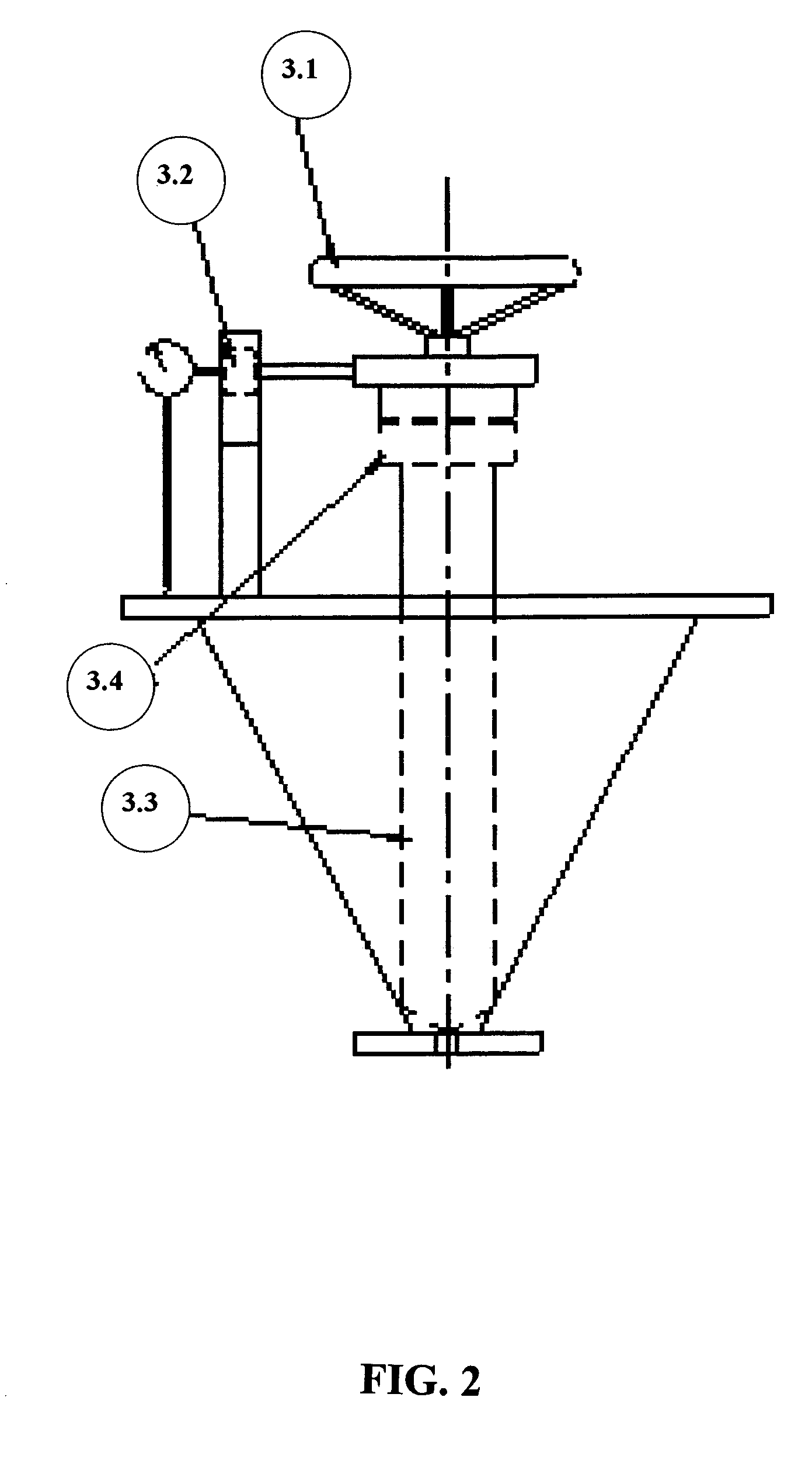
Device for feeding pulverized coal to furnace
a technology for feeding devices and furnaces, which is applied in the direction of lighting and heating apparatus, combustion processes, combustion regulation, etc., can solve the problems of reducing the integrity of samples, reducing the collection efficiency, and said systems are not suitable for experimental furnaces, etc., and achieves stable flow rate, easy operation, and accurate feed consistently
- Summary
- Abstract
- Description
- Claims
- Application Information
AI Technical Summary
Benefits of technology
Problems solved by technology
Method used
Image

Examples
example 1
[0047]Pulverised coal was stored in the feed hopper of capacity 5 kg. Pulverised coal was pushed from the hopper to the distribution chamber with the help of the pneumatic vibrator. The pressure of air for pneumatic vibrator was 1.5 kg / cm2. Compressed primary air rate was 60 liters per minute and pressure was 1.6 kg / cm2. The secondary air rate was 130 liters per minute. From the distribution chamber the pulverised coal and air mixture enterered the furnace reactor. The rate of coal flow as measured by the depth gauge micrometer was 1.5 kg / hr.
example 2
[0048]Pulverised coal was stored in the feed hopper of capacity 5 kg. Pulverised coal was pushed from the hopper to the distribution chamber with the help of the pneumatic vibrator. The pressure of air for pneumatic vibrator was 1.8 kg / cm2. Compressed primary air rate was 65 liters per minute and pressure was 1.7 kg / cm2. The secondary air rate was 140 liters per minute. From the distribution chamber the pulverised coal and air mixture enterered the furnace reactor. The rate of coal flow as measured by the depth gauge micrometer was 2.0 kg / hr.
example 3
[0049]Pulverised coal was stored in the feed hopper of capacity 5 kg. Pulverised coal was pushed from the hopper to the distribution chamber with the help of the pneumatic vibrator. The pressure of air for pneumatic vibrator was 1.3 kg / cm2. Compressed primary air rate was 50 liters per minute and pressure was 1.3 kg / cm2. The secondary air rate was 123 liters per minute. From the distribution chamber the pulverised coal and air mixture enterered the furnace reactor. The rate of coal flow as measured by the depth gauge micrometer was 1.2 kg / hr.
[0050]The main advantages of the device of the present invention for feeding pulverized coal to a furnace are:[0051]1. The feeding system provides consistent and accurate feed.[0052]2. The feeding system is easy to operate.[0053]3. The feeding system is easy to maintain.
PUM
 Abstract
Description
Claims
Application Information