Elbow-type power hand tool

a power hand tool and elbow-type technology, applied in the field of can solve the problems of insufficient space for the aforesaid torque control mechanism and the inability of conventional elbow-type power hand tools to provide torque adjustment functions

Inactive Publication Date: 2005-08-16
MOBILETRON ELECTRONICS
View PDF8 Cites 65 Cited by
  • Summary
  • Abstract
  • Description
  • Claims
  • Application Information

AI Technical Summary

Benefits of technology

[0007]To achieve this objective of the present invention, the elbow-type power hand tool comprises a housing, a power drive mounted inside the housing and having a motor, a planet gear set, and a transmission shaft, a torque controller mounted in the housing for controlling output torque of the transmission shaft, a battery pack mounted in the housing for providing electricity to the ...

Problems solved by technology

The ring gear is rotatably mounted in the housing; however, the ring gear is kept stationary in normal status because the steel balls forced by the spring tightly press on the outer surface of the ring gear to hold the ring gear ...

Method used


Image

  • Elbow-type power hand tool
  • Elbow-type power hand tool
  • Elbow-type power hand tool

Examples


Embodiment Construction

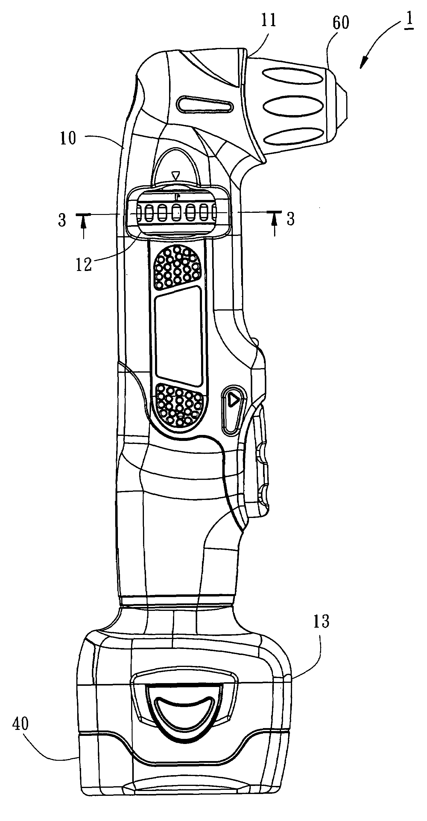
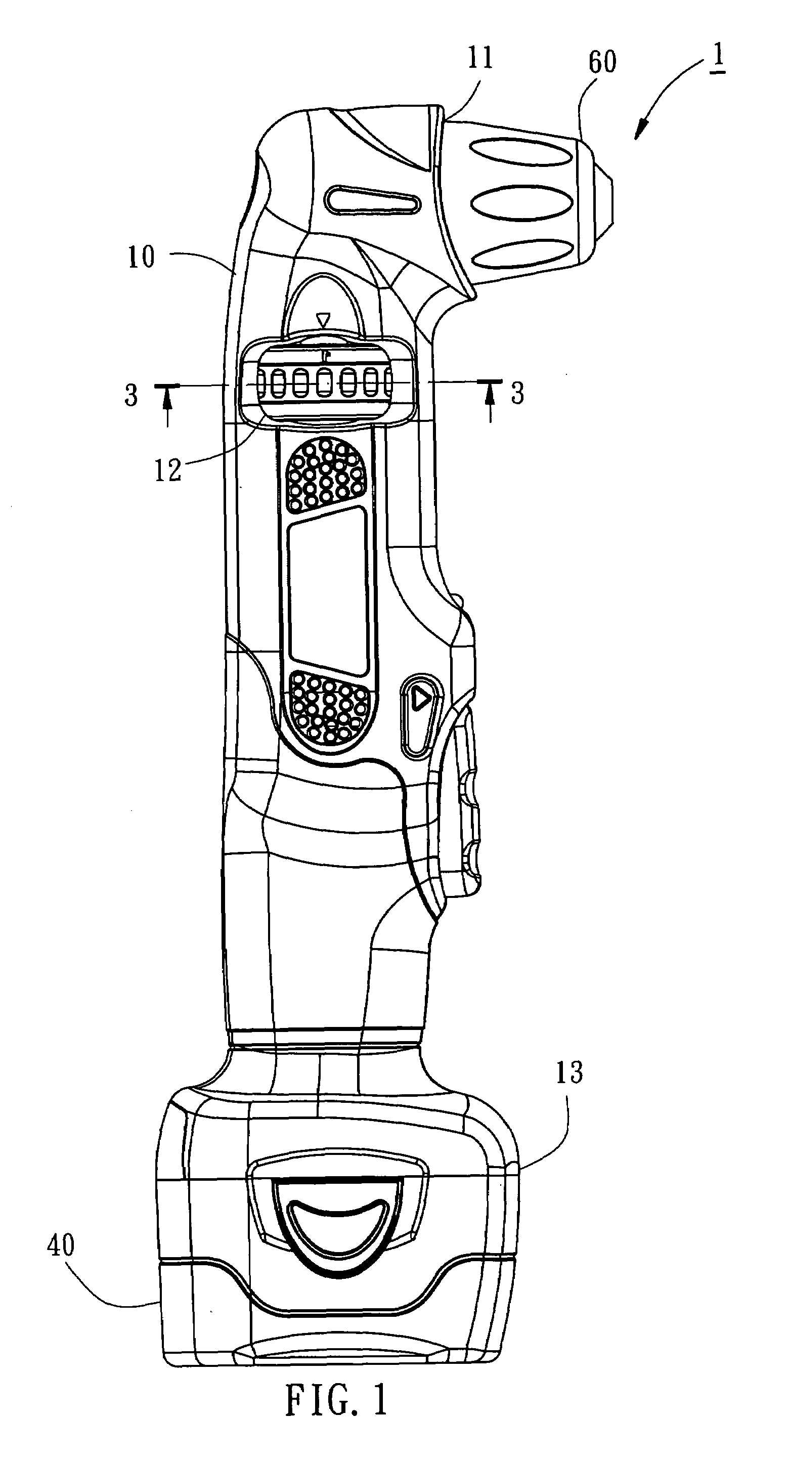
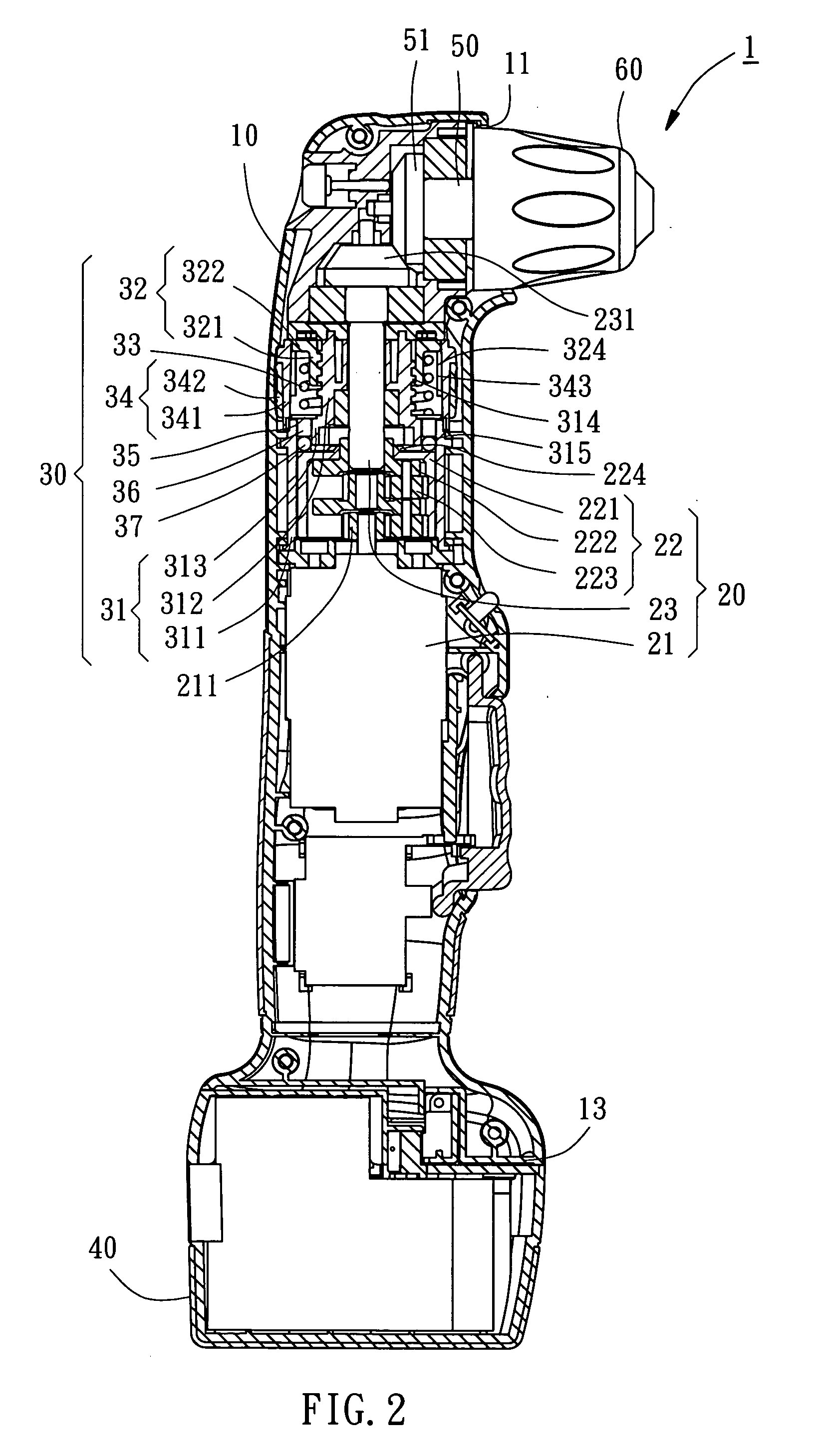
[0011]Referring to FIGS. 1 and 2, an elbow-type power hand tool 1 is shown comprised of a housing 10, a power drive 20, a torque controller 30, a battery pack 40, an output shaft 50, and a chuck assembly 60.

[0012]The housing 10 is a hollow shell having a front opening 11 formed in the front end thereof, two oval side holes 12 bilaterally disposed on the middle near the top side, and an expanded bottom open coupling end 13, which couples the battery pack 40.

[0013]The power drive 20 is mounted in a middle part inside the housing 10, comprising a motor 21 disposed at a rear side, a transmission shaft 23 disposed at a front side, and a planet gear set 22 coupled between the motor 21 and the transmission shaft 23. The motor 21 has the output end thereof mounted with a sun gear 211, which is meshed with the planet gears 223 of the planet gear set 22. The transmission shaft 23 is coupled to the output end of the planet gear set 22. Starting the motor 21 causes the planet gear set 22 to rot...


PUM


Abstract

An elbow-type power hand tool including a housing, a motor, a planet gear set, a transmission shaft, and a torque controller mounted in the housing for controlling output torque of the transmission shaft. The power hand tool including a battery pack mounted in the housing that provides electricity to a power drive, an output shaft coupled to the transmission shaft that extends perpendicular to the transmission shaft, and a chuck assembly coupled to an end of the output shaft remote from the transmission shaft for holding a tool bit.

Description

BACKGROUND OF THE INVENTION[0001]1. Field of the Invention[0002]The present invention relates to a power hand tool and more particularly, to an elbow-type power hand tool, such as cordless power screwdriver, power driller, etc.[0003]2. Description of the Related Art[0004]A conventional linear-type power hand tool, such as cordless power screwdriver, generally comprises a housing, an output shaft axially rotatably extended out of a front end of the housing for coupling a tool bit, a power drive, e.g. a DC motor, mounted inside the housing for rotating the output shaft, and a torque control mechanism, which comprises one or more planet gear trains and is connected between the motor shaft and the output shaft for regulating the output torque of the output shaft. The torque control mechanism further comprises a threaded adjustment ring axially moveably coupled to the housing, a plurality of steel balls rested on an outer surface of the ring gear of the planet gear train, and a coil spri...

Claims


Application Information

Patent Timeline
IPC IPC(8): B25B21/00
CPCB25B21/00
Inventor LAI, YING-HUI
Owner MOBILETRON ELECTRONICS
Why Eureka
Try Eureka