
Method of winding yarns to form frustoconical yarn packages

Inactive Publication Date: 2005-08-16
SAINT GOBAIN TECH FABRICS EURO
View PDF15 Cites 1 Cited by
  • Summary
  • Abstract
  • Description
  • Claims
  • Application Information

AI Technical Summary

Benefits of technology

[0019]Furthermore, the eyelet has an opening, for passage of the yarn, which is much too large compared with the diameter of the said yarn for allowing precise guiding of the yarn deposition.
[0020]The object of the invention is therefore to obviate the aforementioned drawbacks and to provide a method of obtaining a frustoconical bobbin which has good mechanical strength and can be easily unwound, the winding taking place in a horizontal plane without requiring significant modifications to the conventional means of implementation already existing.
[0036]The advantage of creating a waviness in the yarn is that it allows the crossover angle to be optimized so as to reduce the risk of forming rings when unwinding it.

Problems solved by technology

However, this method requires, on the one hand, four separate winding steps and, on the other hand, a change of inclination at which the layers of yarn are deposited during these steps, something which does not simplify its implementation.
In addition, this winding method produces an angle of build of the first layers with respect to the axis of the bobbin which is too great for a winding operation such as that desired, namely the winding of glass yarn coming from a bushing.
This large angle of build creates large circumferential variations between the circumference of the base cone and the circumference obtained at the end of the first step of the method; now, when winding glass yarn whose drawing speed must be kept constant in order to keep the yarn count constant, such circumferential variations would impose consequent variations in the speed of the bobbin support both when it is accelerating and when it is decelerating, something which is not easily achievable physically.
However, this guiding mode cannot be envisaged for guiding a glass yarn for the purpose of winding it, particularly a yarn coming directly from a bushing.
This is because, in the event of breakage of the filaments coming from the bushing, it would prove to be too complicated to restart the winding operation; it is too difficult after collecting the filaments to pass them again through the eyelet, which has a closed circumference.
It is also impossible with an eyelet to transfer the winding of the yarn from one bobbin onto another bobbin without having to break the yarn, which impairs the optimization of the production times.

Method used


Image

  • Method of winding yarns to form frustoconical yarn packages
  • Method of winding yarns to form frustoconical yarn packages
  • Method of winding yarns to form frustoconical yarn packages

Examples


Embodiment Construction

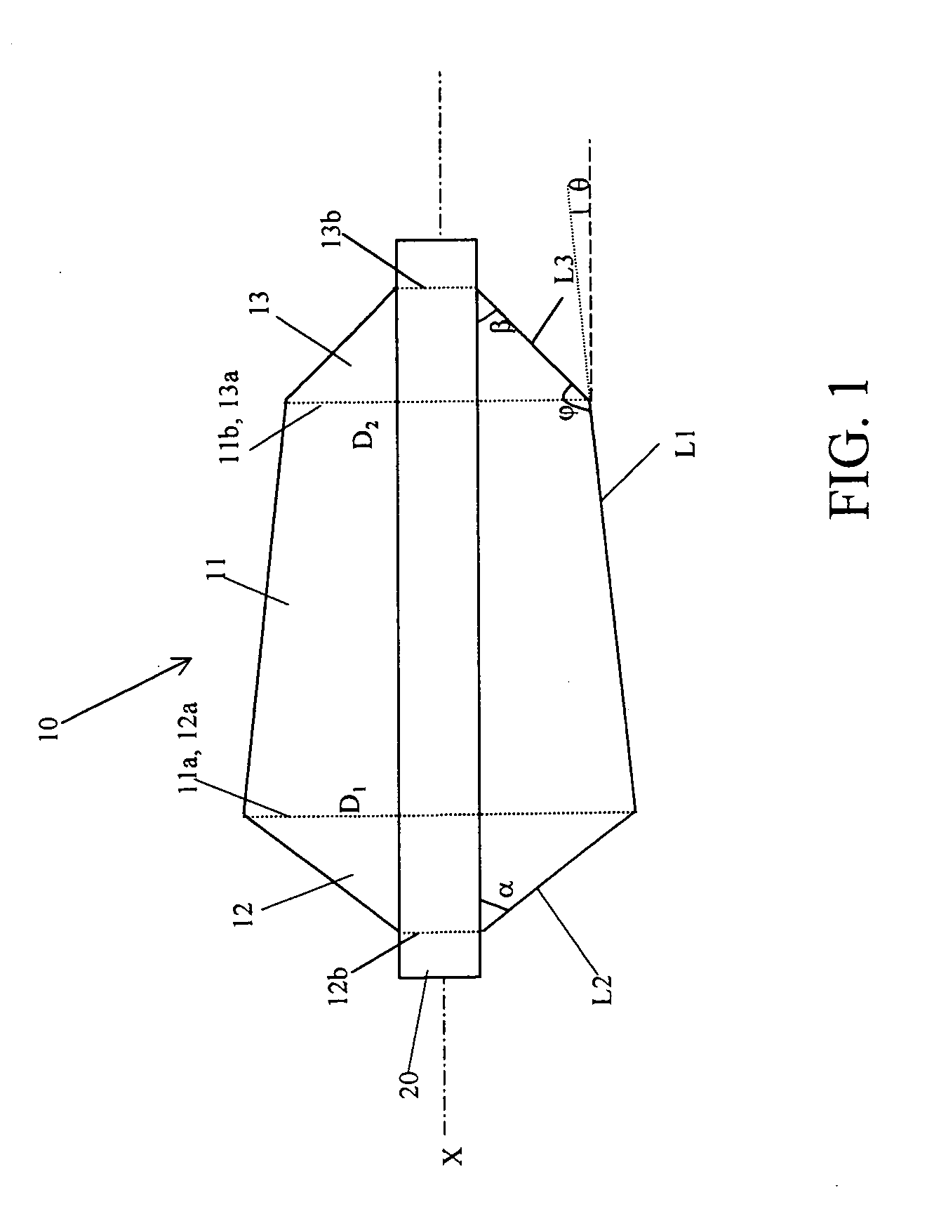
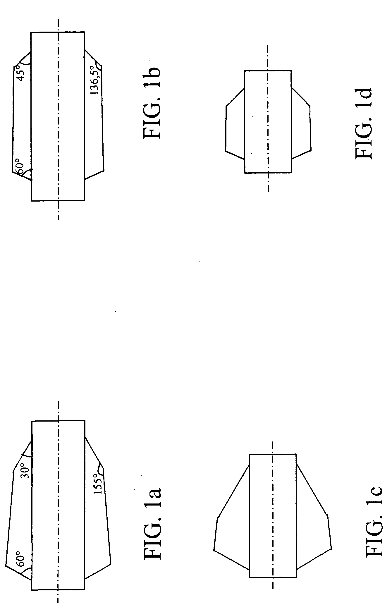
[0046]FIG. 1 shows a frustoconical bobbin 10 produced according to the invention, obtained by winding a yarn around a cylindrical support 20 of longitudinal axis X, the support being without any flange at its ends. The wound yarn is glass yarn for example.

[0047]The bobbin 10 comprises a bobbin body 11 of frustoconical shape and two truncated cones 12 and 13 located respectively at the two longitudinal opposed ends of the bobbin, on each side of the bobbin body 11.

[0048]The bobbin body 11 has a base 11a of diameter D1 and a terminal section 11b of diameter D2 less than the diameter D1, the generatrix L1 of the frustoconical body 11 thus being inclined with respect to the X axis at an angle θ.

[0049]The end truncated cone 12 formed firstly during the winding operation will be called hereafter the base cone. It has a base 12a consisting of the base 11a of the bobbin body 11 of diameter D1 and a termination 12b, the diameter of which corresponds to that of the support 20. The truncated c...


PUM


Abstract

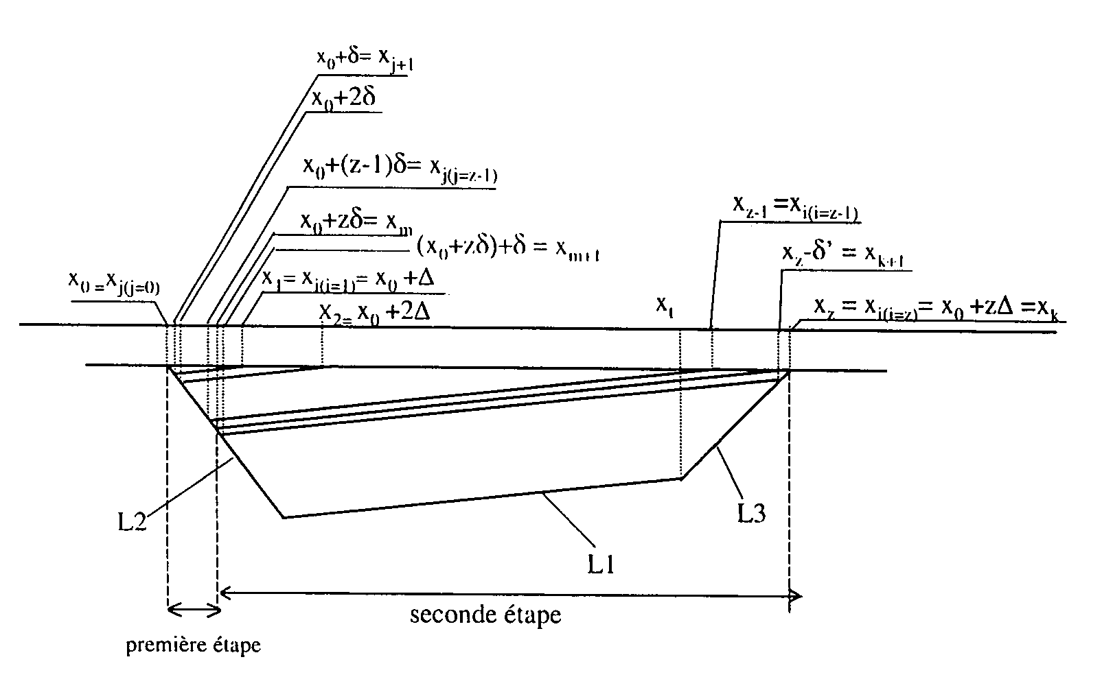
Method of manufacturing a frustoconical bobbin which is obtained by depositing superposed layers of a yarn onto a cylindrical support of longitudinal axis and comprises a base cone having a generatrix, an unwind cone having a generatrix and a main body having a generatrix which is inclined with respect to the axis and joins the two generatrices of the two cones. The method is characterized in that it comprises two rules governing the movement of the yarn guide, a first rule which is used to form part of the base cone, the last layer of yarn deposited according to this first rule going as far as the end of the unwind cone, and a second rule which is used to terminate the said base cone that has been started and, concomitantly, to form the main body and the unwind cone, the first layer of yarn deposited according to the second rule being parallel to the last layer deposited according to the first rule.

Description

BACKGROUND OF THE INVENTION[0001]1. Field of the Invention[0002]The invention relates to the manufacture of yarn packages for yarns such as glass yarns, and more particularly to the manufacture of frustoconical packages.[0003]2. Description of Related Art[0004]Yarn packages in the form of bobbins are a standard means of temporarily storing yarn, in order subsequently for it to be fed into yarn-handling machines, for example textile machines.[0005]In the case of glass yarns, glass filaments obtained by molten glass flowing through orifices in a bushing are drawn. Next, these filaments are coated with a sizing composition by a coater so as to facilitate the fiberizing and the collecting of the filaments into a yarn and to increase their mechanical properties, especially upon ageing. These filaments are then brought together into a combining device in order to create the yarn to be wound. The yarn coming from the combining device is wound around a support which lies in a horizontal pla...

Claims


Application Information

Patent Timeline
IPC IPC(8): B65H54/28B65H55/00B65H54/32B65H55/04
CPCB65H54/325B65H55/04B65H2701/3122
Inventor MAGER, GUENTHERMOIREAU, PATRICK
Owner SAINT GOBAIN TECH FABRICS EURO
Learn More