Vehicular lamp

a technology for vehicular lamps and translucent parts, which is applied in fixed installations, lighting and heating apparatus, and support devices for lighting, etc., can solve the problems of difficult to provide uniform shining of translucent parts, and extremely limited configuration of translucent parts, so as to achieve the effect of increasing the brightness of vehicular lamps

Inactive Publication Date: 2005-08-16
KOITO MFG CO LTD
View PDF8 Cites 24 Cited by
  • Summary
  • Abstract
  • Description
  • Claims
  • Application Information

AI Technical Summary

Benefits of technology

[0009]It is an object of the present invention to provide a vehicular lamp that has an LED light source and a translucent member, in which the translucent member appears to be lit uniformly when the LED light source, when it is lit, is observed from the front of the lamp and in which the lamp has an increased freedom of design choice with respect to the shape of the translucent member.
[0030]The vehicular lamp according to the present invention can include only one set of an LED light source and a translucent member or a plurality of sets of LED light sources and translucent members. In the event that a plurality of sets of LED light sources and translucent members are provided at a plurality of locations, a further increase in brightness of the vehicular lamp is attained. In the present invention, the length of the pillar-shaped portion of the translucent portion can be selectively set, and this easily makes it possible to arrange the plurality of LED light sources and translucent members in a desired layout in accordance with the lamp shape and the like.

Problems solved by technology

This causes a problem.
When the translucent member is observed from the front of the lamp when the LED light source is lit, the appearance of a uniform shining of the translucent member is not easily provided.
This causes another problem.
The configuration of the translucent member is extremely limited.

Method used


Image

  • Vehicular lamp
  • Vehicular lamp
  • Vehicular lamp

Examples


Embodiment Construction

[0040]Hereafter, one embodiment according to the present invention will be described with reference to the accompanying drawings.

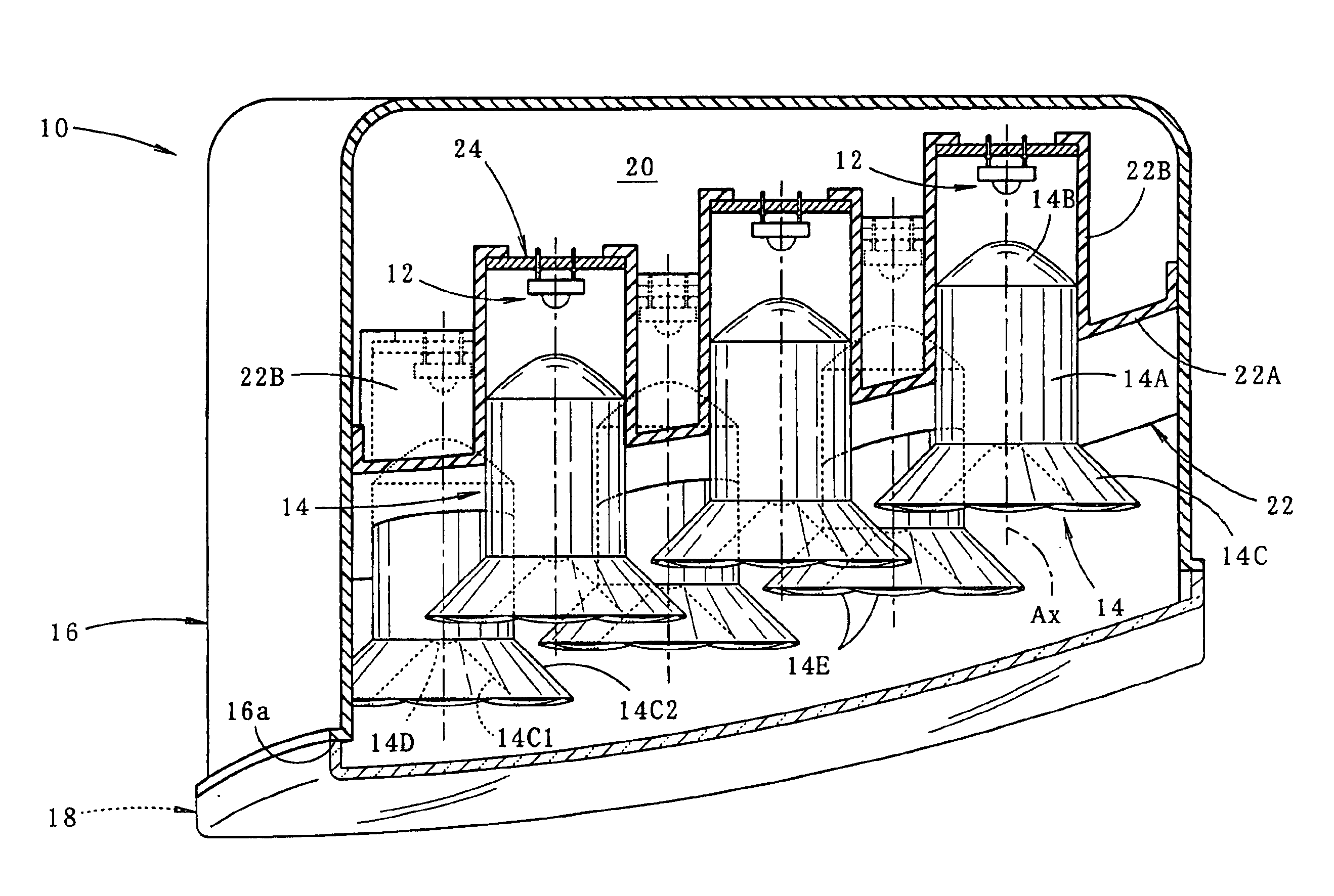
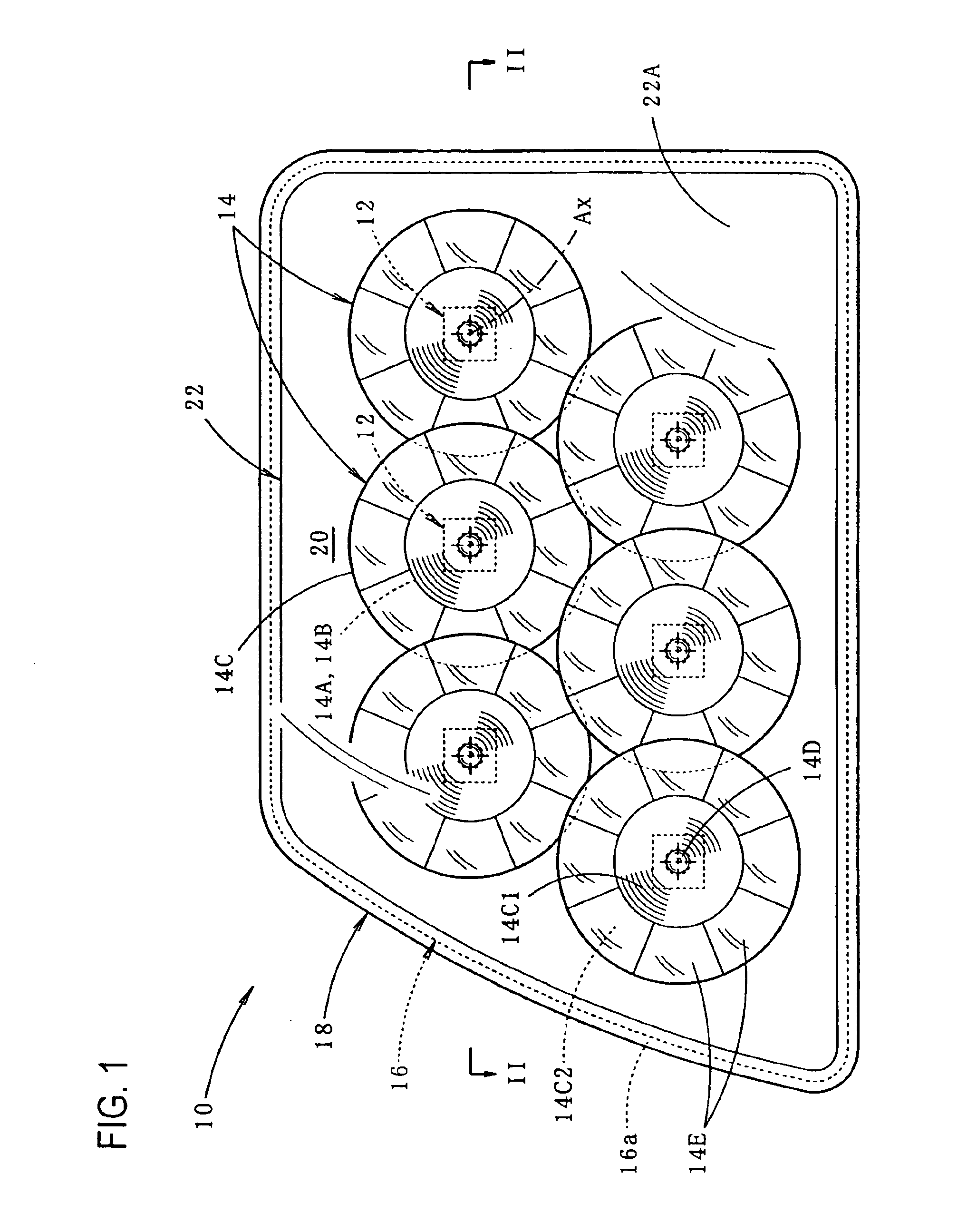
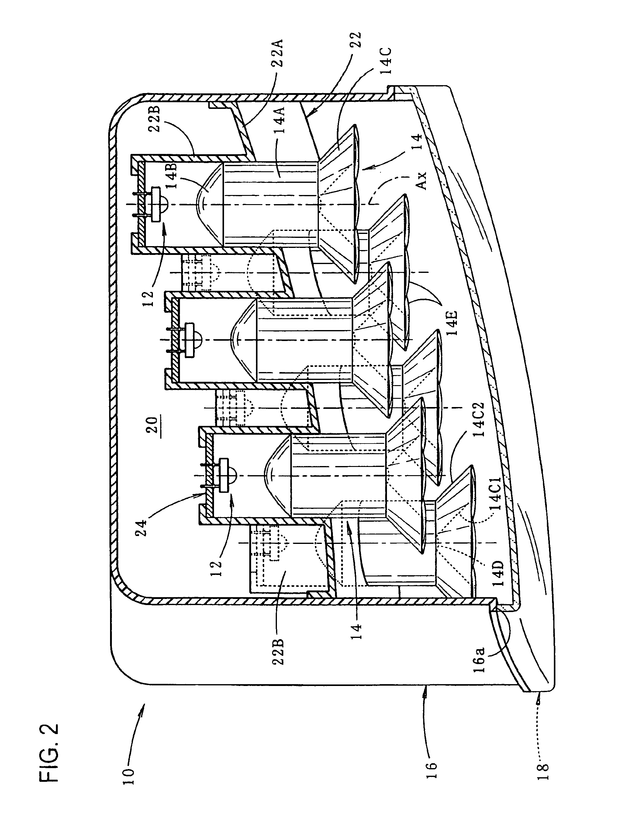
[0041]As illustrated in FIGS. 1 and 2, the vehicular lamp 10 of the shown embodiment is a tail lamp provided on the right rear-end portion of a vehicle, and it has a plurality of sets (six sets) of LED light sources 12 and translucent members 14 housed in a lamp chamber 20 constituted by a lamp body 16 and a plain-configured translucent cover 18 which is attached to a front-end opening 16a of the lamp body 16 (the “front-end opening 16a of the lamp body 16” being a “rear-end opening” for the vehicle).

[0042]The lamp chamber 20 incorporates a supporting member 22 which supports the plurality of sets of LED light sources 12 and translucent members 14. The supporting member 22 includes a panel portion 22A, which is formed so as to substantially follow the curved shape of the translucent cover 18, and cylindrical portions 22B, which protrude backward (of the la...


PUM


Abstract

A vehicular lamp with an LED light source in which the translucent member includes a pillar-shaped portion that has at its rear end a condenser lens portion and at its front end a substantially bowl-configured parallel translation controlling portion. Light from the LED light source is formed into parallel light fluxes by the condenser lens portion, and this parallel light fluxes strike the pillar-shaped portion, and then the light path of the parallel light fluxes is formed into a crank configuration in a direction in which the light path separates from the axis of the pillar-shaped portion, thus allowing the reflected light from the parallel translation controlling portion to be resulted in parallel light fluxes that travels toward the front of the lamp and allowing the translucent member to appear to be lit uniformly.

Description

BACKGROUND OF THE INVENTION[0001]1. Field of the Invention[0002]The present invention relates to a vehicle lamp that has an LED (Light Emitting Diode) light source.[0003]2. Prior Art[0004]Recently, vehicle lamps with an LED light source have been frequently employed. In the vehicle lamp disclosed in Japanese Utility-Model Application Laid-Open (Kokai) No. 61-153201, a translucent member is placed in the vicinity of the front of an LED light source disposed so as to face in the forward direction of the lamp, and light from the LED light source is internally reflected plurality of times by this translucent member and emitted toward the front of the lamp.[0005]With an adoption of such a lamp structure, it is possible to allow the light from the LED light source to appear to be lit over a large light emitting area.[0006]However, in the above-described vehicular lamp, the light from the LED light source reaches the translucent member as scattered light, and the angles of the incident lig...

Claims


Application Information

Patent Timeline
Patent Type & Authority Patents(United States)
IPC IPC(8): F21V7/00F21S8/10F21V13/00F21V13/04F21W101/12F21W101/14F21Y101/02
CPCF21S48/215F21S48/2225F21S48/236F21S48/24F21V7/0091F21S43/14F21S43/235F21S43/315F21S43/40
Inventor AMANO, YASUYUKI
Owner KOITO MFG CO LTD
Why Eureka
Try Eureka