
Coaxial cable connector with viewing window

Active Publication Date: 2005-08-16
HOLLAND ELECTRONICS
View PDF3 Cites 132 Cited by
  • Summary
  • Abstract
  • Description
  • Claims
  • Application Information

AI Technical Summary

Benefits of technology

[0014]When the prepared end of a coaxial cable is inserted into the trailing end of the compression sleeve conduit, and advanced forwardly through the slotted body portion, the trailing end of the tubular shank forces the cable jacket and braid over the relatively low profile barb into an annular space between the shank and the body portion to overlie the tubular shank forward of the barb as well as over the barb. The cable is further advanced into the connector until the leading end of the braided shielding underlies the forward end of the slot as can be determined visually. When it is determined, by visual inspection, that the prepared end of the coaxial cable is fully advanced into the conduit within the body portion, advancement of the compression sleeve over the body portion compresses the cable jacket in two places: (a) between the compression sleeve and the barb on the tubular shank; and (b) between the tubular shank and the gripping ridges within the conduit of the slotted body portion. Further advancement of the compression sleeve is terminated when the annular ridge within the conduit of the compression sleeve “snaps” into, and engages, the second, middle groove in the outer surface of the body portion. The cable jacket and braid are radially compressed where they overlie the barb and where they underlie the gripping ridges, as well as over the barb, thereby providing a stable two-point connection.

Problems solved by technology

While the innovative plethora of prior art connectors, some of which are disclosed above, provide improved moisture sealing and / or RF leakage characteristics, all have inherent limitations.
The steps required in order to provide a secure, sealing engagement between a connector and a coaxial cable include opportunities for installation errors to occur.
If the installer fails to completely compress the connector, especially in the final 20 percent of the compressive range, the connector may come loose.
In addition, if the cable is not fully inserted into the conduit, the connector may come loose and / or the electrical connection may fail.

Method used


Image

  • Coaxial cable connector with viewing window
  • Coaxial cable connector with viewing window
  • Coaxial cable connector with viewing window

Examples


Embodiment Construction

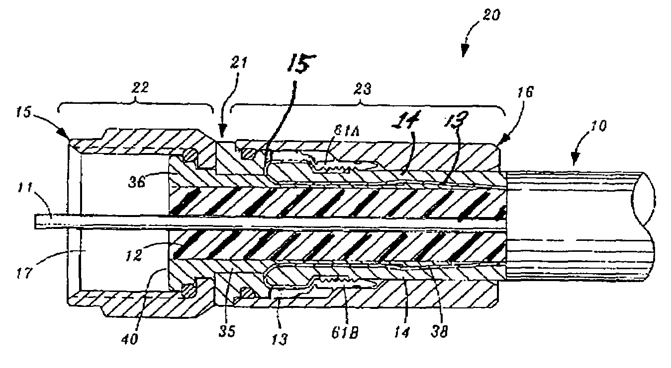
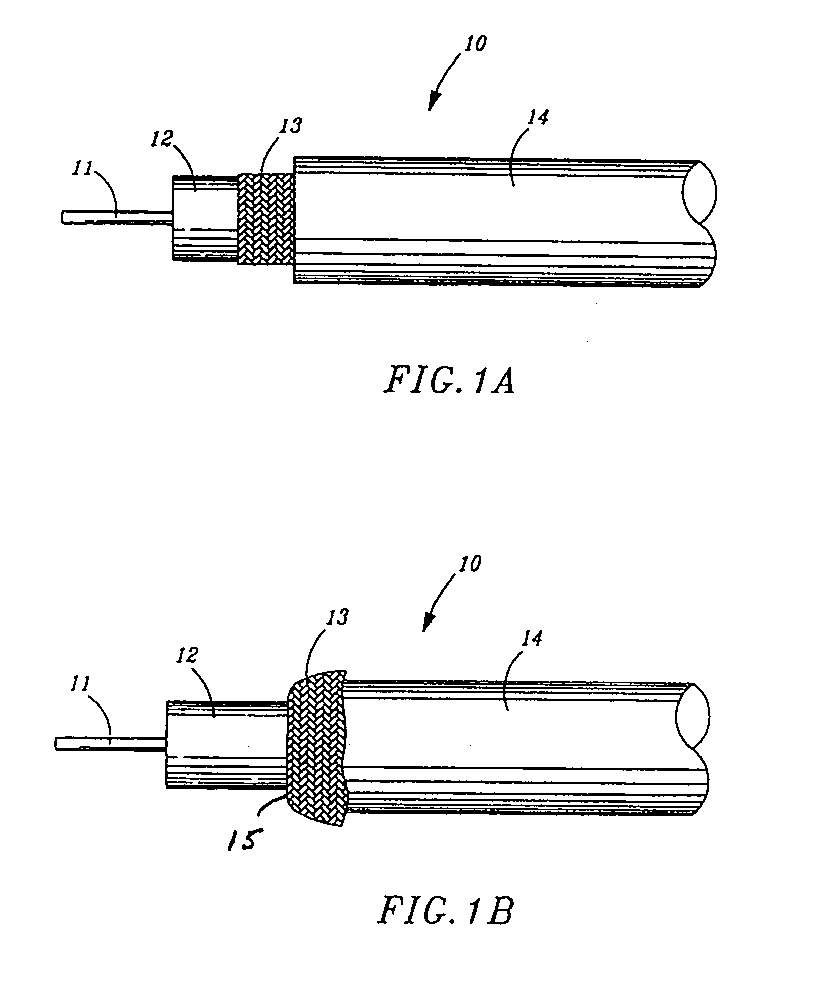
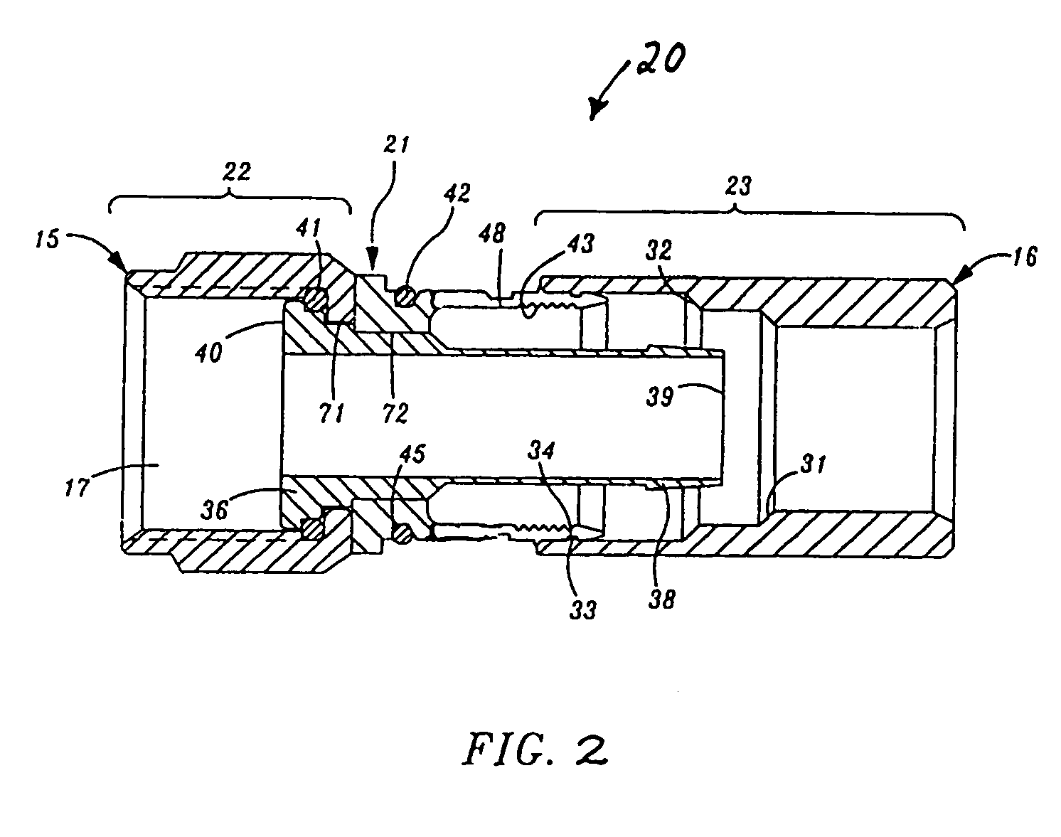
[0023]Turning now to FIG. 1a, the partially prepared (i.e., stripped) end of a coaxial cable 10 is shown in elevational view. Prior to coupling a coaxial cable to a male connector, the end of the cable to receive the connector must first be prepared. It will be understood by the artisan that the preparation of the end of the cable will be in accordance with the type of male coaxial cable connector that the cable 10 will be attached to (i.e., F-type, BNC, RCA, etc.). A cutting tool (not shown) is used by an installer to expose a portion of the central conductor 11, a length of the dielectric core 12 and a conductive (grounding) braid 13, as shown in FIG. 1a. Again, the respective lengths of each of the elements comprising the coaxial cable 10 that are exposed by the cutting tool will depend on the particular type of male connector to be attached thereto and are in accordance with industry standards. Following exposure of the conductive braid 13, the exposed portion of conductive brai...


PUM


Abstract

A male compression-type coaxial cable connector having a leading end, a trailing end and integral construction is described. The connector includes a nut at the leading end of the connector that is adapted to matingly engage an F, BNC, SMB, MCX or RCA-type female connector. The connector also has a tubular shank, a slotted body portion concentrically mounted to overlie the tubular shank and a compression sleeve slidably attached to the slotted body portion the compression sleeve being disposed on the trailing end of the connector. The trailing end of the connector has an axial conduit therein concentrically disposed around the tubular shank. When the prepared end of a coaxial cable is inserted into the trailing end of the axial conduit and fully advanced into the axial conduit, subsequent advancement of the compression sleeve over the slotted body portion, with the assistance of a compression tool, compresses the cable jacket and braid providing secure attachment. The elongate slots in the body portion provide a viewing window that enables an installer to visually determine when the prepared end of the cable is fully inserted into the axial conduit prior to compression.

Description

BACKGROUND OF THE INVENTION[0001]1. Field of the Invention[0002]The present invention relates to male coaxial cable connectors operable for electrically connecting a coaxial cable to a mating female port, and, more particularly, to a male coaxial cable connector having a viewing port to enable the installer to visually determine when the prepared end of a coaxial cable is fully inserted into the connector prior to the attachment of the cable thereto.[0003]2. Prior Art[0004]Connectors adapted to form a secure, electrically conductive connection between a coaxial cable and a threaded female port have been developed. Such prior art connectors are discussed, for example, in U.S. Pat. No. 6,217,383 to Holland et al., U.S. Pat. No. 6,676,446, U.S. Pat. No. 6,153,830 and U.S. Pat. No. 6,558,194 to Montena, U.S. Pat. No. 5,024,605 to Ming-Hua, U.S. Pat. No. U.S. Pat. No. 4,280,749 to Hemmer, U.S. Pat. No. 4,593,964 to Forney, Jr. et al., U.S. Pat. No. 5,007,861 to Stirling, U.S. Pat. No. 5,...

Claims


Application Information

Patent Timeline
IPC IPC(8): H01R9/05
CPCH01R9/0518
Inventor HOLLAND, MICHAEL
Owner HOLLAND ELECTRONICS
Features
  • Generate Ideas
  • Intellectual Property
  • Life Sciences
  • Materials
  • Tech Scout
  • Unparalleled Data Quality
  • Higher Quality Content
  • 60% Fewer Hallucinations
Learn More