Method of manufacturing a spacer of an electrically driven water purification apparatus

a technology of electrical drive and water purification apparatus, which is applied in the direction of electrodialysis, separation processes, other domestic objects, etc., can solve the problems of poor mechanical sealing characteristics, loss of valuable product water, and insufficient sealing characteristics, and achieve the effect of facilitating d-flow

Inactive Publication Date: 2005-08-16
E CELL
View PDF43 Cites 27 Cited by
  • Summary
  • Abstract
  • Description
  • Claims
  • Application Information

AI Technical Summary

Benefits of technology

[0016]In another aspect, the present invention provides an electrically driven membrane process apparatus having a first spacer and a frame member separated by an ion exchange membrane, the first spacer comprising a first surface having a first throughbore for flowing an aqueous liquid, the frame member comprising a second surface, a second throughbore extending through the second surface and communicating with the first throughbore, and a continuous flange depending from the second surface and surrounding the second throughbore, the flange pinching a portion of the first surface surrounding the first throughbore. The second throughbore can facilitate D-flow.
[0017]In a further aspect, the present invention provides an electrically driven membrane process apparatus comprising an electrically driven membrane process apparatus comprising a first spacer having a first perimeter having a surface with a first inner peripheral edge defining a first opening, a recess formed on the first inner peripheral edge, and a mesh extending across the first opening and joined to the first inner peripheral edge, a second spacer having a second perimeter having a surface with a second inner peripheral edge defining a second opening, an ion exchange membrane fitted within the recess and extending across the first opening and having a surface portion engaged to the second perimeter inwardly of the first inner peripheral edge, and a ridge depending from the second perimeter of the second spacer and compressing the surface portion of the ion exchange membrane against the mesh, thereby preventing or reducing likelihood of buckling of the mesh.

Problems solved by technology

Unfortunately, this alone has not provided adequate sealing characteristics.
Unfortunately, as a result of exposure to typical operating conditions, the seal formed thereby is prone to leakage, thereby causing the loss of valuable product water.
This arises from the intrinsic moisture permeability of the IX membranes and because of poor mechanical sealing characteristics.
Unfortunately, during assembly of the device, it is known to be difficult to maintain ion exchange membranes in a desired alignment relative to associated spacers.
Further, during operation and consequent exposure to relatively high internal pressure or differential pressures within the device, ion exchange membranes may move and become displaced from a desired position relative to their associated spacers.
Failure to maintain such a desired position may compromise the sealing of the associated chamber.
However, this provides a further potential source for leakage and, therefore, compromises sealing of the device.
The material of construction of known spacers is also known to be detrimental to the sealing characteristics of this arrangement.
Unfortunately, such thermoplastic materials are prone to stress relaxation or compression set.
As a result, over time, because of exposure to the relatively high internal pressures, such spacers, and particularly their o-ring type sealing members, lose their resiliency, thereby compromising their ability to maintain adequate seals with adjacent surfaces.

Method used


Image

  • Method of manufacturing a spacer of an electrically driven water purification apparatus
  • Method of manufacturing a spacer of an electrically driven water purification apparatus
  • Method of manufacturing a spacer of an electrically driven water purification apparatus

Examples


Embodiment Construction

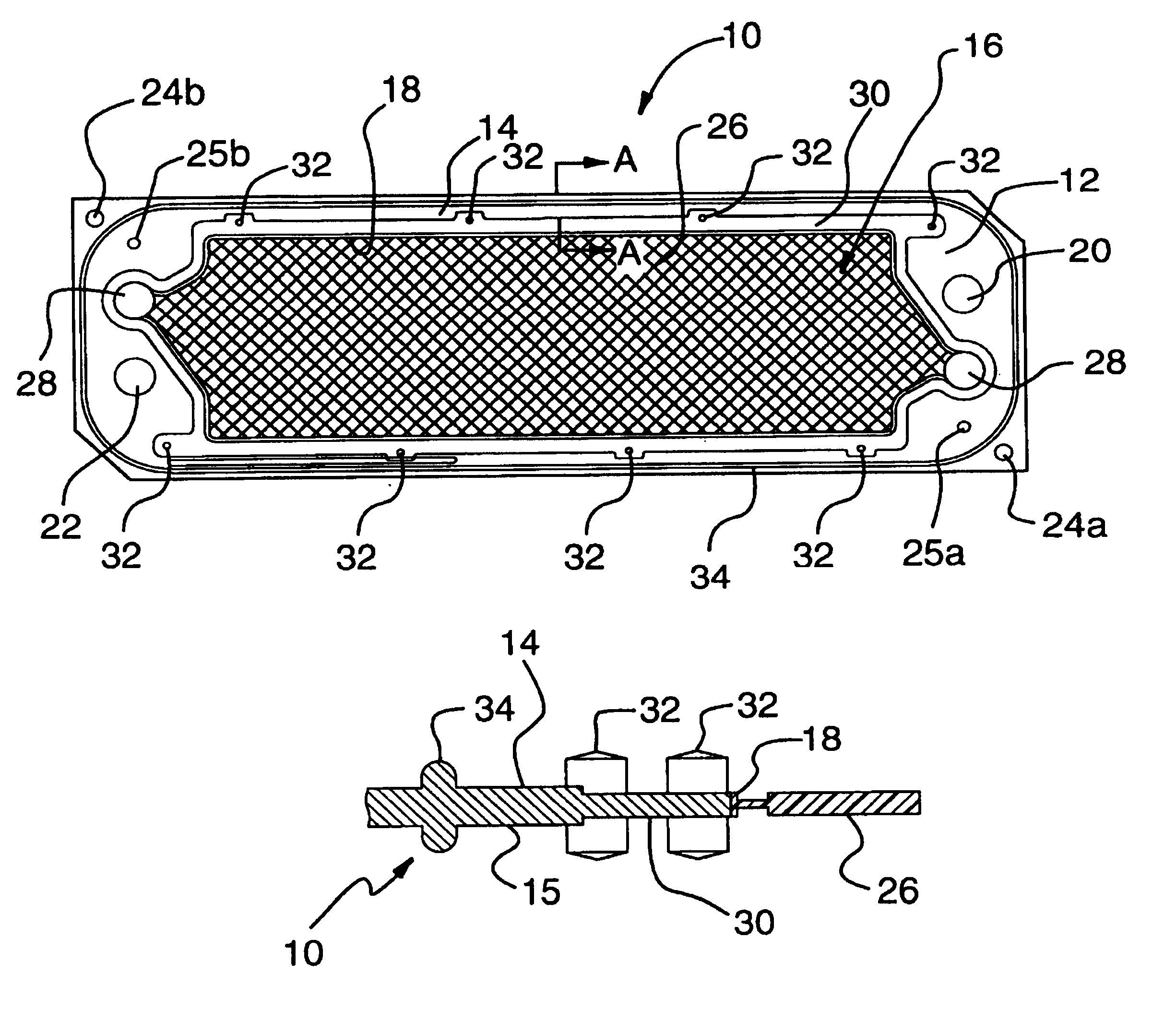
[0039]The present invention provides a spacer of a filter press type electrically driven water purification apparatus, such as an electrodyalisis unit or an electrodeionization unit. Electrodeionization units include those with ion exchange resin in the concentrating chamber. The spacer of the present invention can also be used in other electrically driven membrane process apparati of the filter press type. An example of another electrically driven membrane process which falls within the purview of this invention is salt splitting. The invention will hereafter be explained with reference to an electrically driven water purification apparatus.

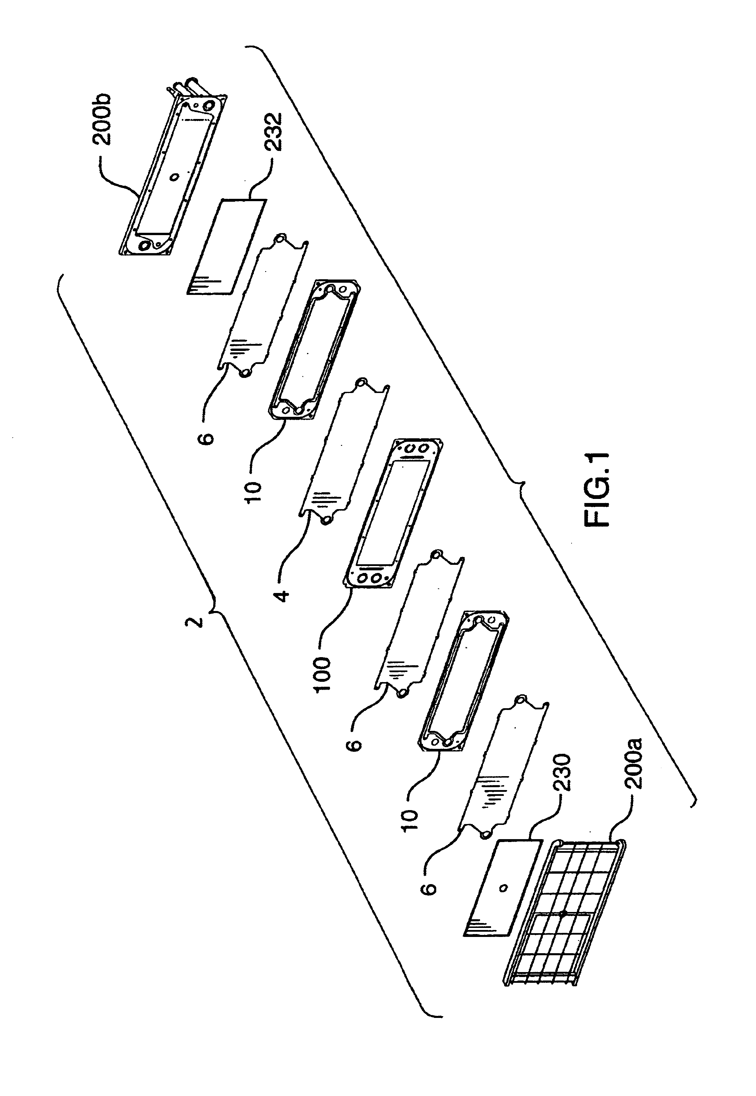
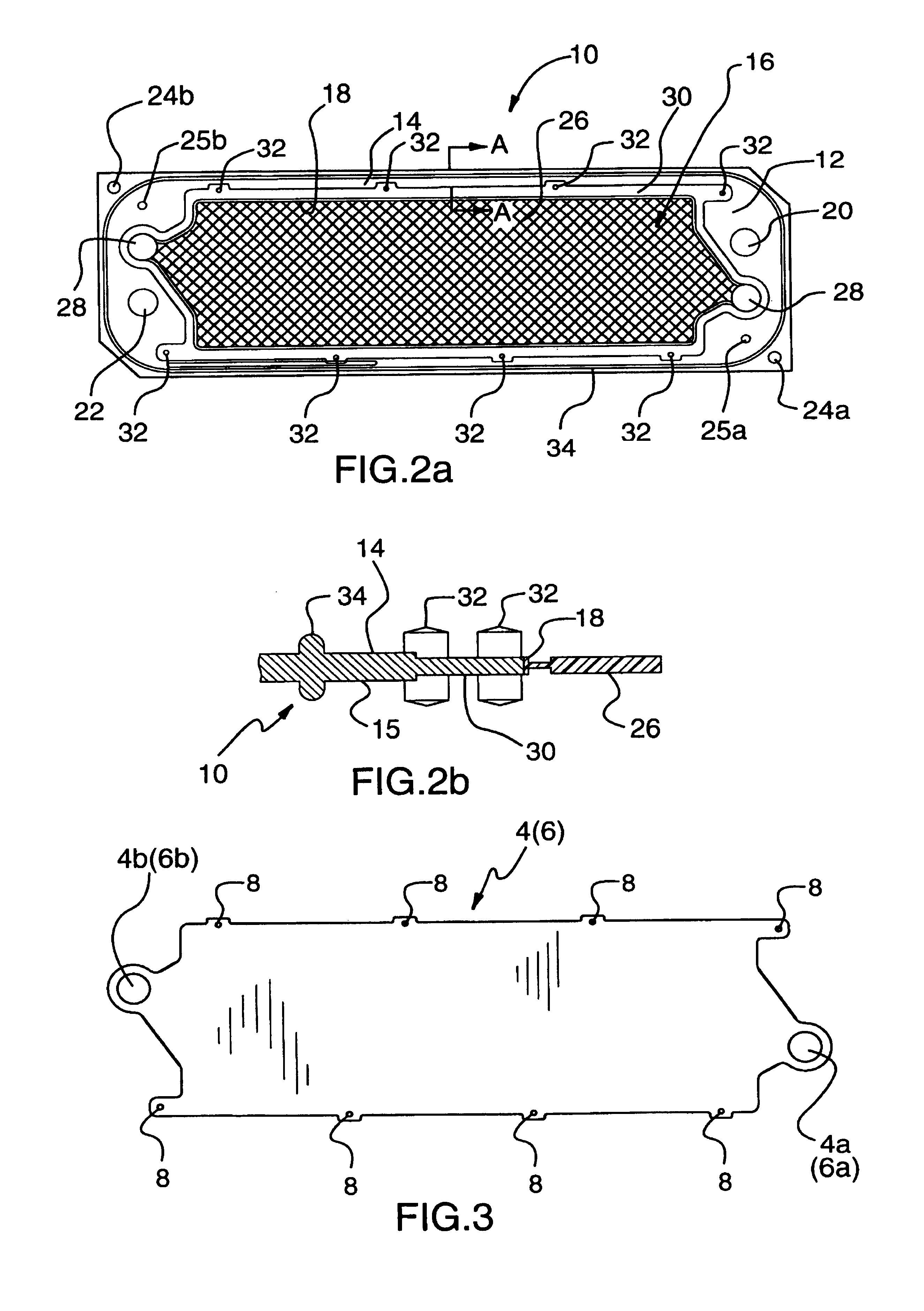
[0040]Referring to FIG. 1, a typical electrically driven water purification apparatus 2 comprises alternating anion exchange membranes 4 and cation exchange membranes 6. Spacers 10 and 100 are provided in between the alternating cation and anion exchange membranes to help define alternating diluting chambers (“D-chambers”) and concentrating cham...


PUM

PropertyMeasurementUnit
perimeteraaaaaaaaaa
permeationaaaaaaaaaa
preferential permeationaaaaaaaaaa

Abstract

An electrically driven membrane process apparatus is provided comprising a first spacer having a perimeter having a surface with an inner peripheral edge defining an opening, and a recess formed on the inner peripheral edge, and an ion exchange membrane having an outer edge fitted within the recess. The spacer can further comprise a plurality of bosses and an ion exchange membrane having a corresponding plurality of apertures for receiving the bosses. The spacer can include a plastic mesh consisting essentially of polypropylene or polyethylene, and a perimeter surrounding the plastic mesh, the perimeter comprising material selected from the group consisting of thermoplastic vulcanizates and thermoplastic elastomeric olefins. The spacer can have an upstanding seal member depending therefrom, received by groove within a corresponding frame member. A second spacer is also provided having a continuous flange depending from its surface and surrounding a throughbore, for pinching a portion of the first spacer. A method of injection molding a thin plastic part comprising a perimeter having an inner peripheral edge and a mesh joined to the inner peripheral edge is also provided including the steps of (a) providing first and second mold halves, each of the mold halves having an interior surface and a continuous ridge depending therefrom; and (b) pinching opposite side of the mesh between the ridges to form a flow barrier.

Description

RELATED APPLICATIONS[0001]This application is a continuation-in-part of application Ser. No. 09 / 327,598 filed Jun. 8, 1999 now issued as U.S. Pat. No. 6,235,166, and also claims the benefit of PCT / CA00 / 00687 filed Jun. 8, 2000.FIELD OF THE INVENTION[0002]The present invention relates to electrically driven water purification devices and, in particular, to novel sealing means to facilitate sealing of such devices.DESCRIPTION OF THE RELATED ART[0003]Water purification devices of the filter press type which purify water by electrically driven membrane processes, such as electrodyalisis or electrodeionization, comprise individual chambers bounded by ion exchange membranes. Typically, each of the chambers is defined on one side by a membrane disposed to the preferential permeation of dissolved cation species (cation exchange membrane) and on an opposite side by a membrane disposed to the preferential permeation of dissolved anion species (anion exchange membrane).[0004]Water to be purifi...

Claims


Application Information

Patent Timeline
Patent Type & Authority Patents(United States)
IPC IPC(8): B01D61/42B01D63/08B01D61/50B01D65/00B29C45/14B01D61/46B01D63/00C02F1/469
CPCB01D61/50B01D63/081B01D65/003B29C45/14336
Inventor COTTON, BILLTOWE, GLENNYAGAR, MATHEW J.ERBICEANU, EDUARD
Owner E CELL
Why Eureka
Try Eureka