Manufacturing method of CPP type magnetic sensor having current-squeezing path

a technology of magnetic sensor and manufacturing method, which is applied in the manufacture of flux-sensitive heads, instruments, record information storage, etc., to achieve the effect of superior alignment accuracy and easy and accurate formation

Inactive Publication Date: 2005-08-16
TDK CORPARATION
View PDF16 Cites 8 Cited by
  • Summary
  • Abstract
  • Description
  • Claims
  • Application Information

AI Technical Summary

Benefits of technology

[0046]In addition, according to the present invention, between the step (c) and the step (d), it is preferable that the second gap layers, the bias layers, and the third gap layers be formed sequentially using a mask layer for defining the multilayer film to have a predetermined shape. Accordingly, the second gap layers, the third gap layers, and the bias layers can be easily and accurately formed at a predetermined position with superior alignment accuracy.

Problems solved by technology

In addition, unlike the related technique shown in FIGS. 16 and 17, an opening portion extending to the multilayer film is not formed in the first gap layer after the formation of the first gap layer, and hence the problem in that the upper surface of the multilayer film is damaged by etching also will not occur.

Method used


Image

  • Manufacturing method of CPP type magnetic sensor having current-squeezing path
  • Manufacturing method of CPP type magnetic sensor having current-squeezing path
  • Manufacturing method of CPP type magnetic sensor having current-squeezing path

Examples


Embodiment Construction

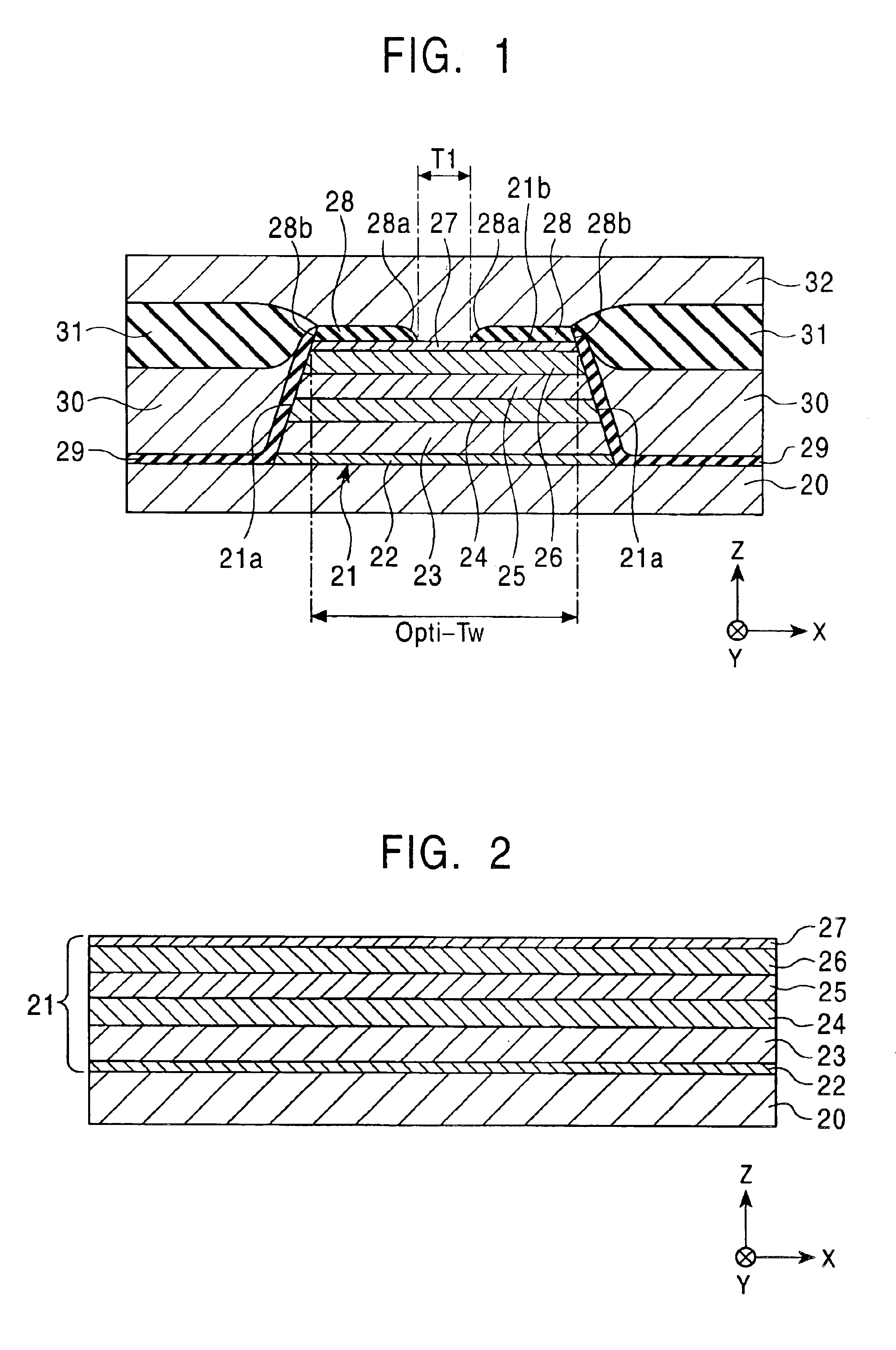
[0064]FIG. 1 is a partial cross-sectional view of a magnetic sensor of an embodiment according to the present invention, the magnetic sensor being taken along a parallel direction (direction parallel to an X-Y face) to a face facing a recording medium and being viewed therefrom.

[0065]The magnetic sensor shown in FIG. 1 is a GMR head for reproducing external signals recorded on a recording medium. Although not shown in the figure, an inductive head used for recording may be provided on this magnetic sensor.

[0066]In this embodiment, a “track width direction” indicates the direction parallel to the X direction shown in the figure, and this direction is a width direction of a region in which a magnetization direction is varied by an external magnetic field and, for example, is a magnetization direction of a free magnetic layer when an external magnetic field is not applied. In addition, a “height direction” indicates the direction parallel to the Y direction shown in the figure and coin...


PUM

PropertyMeasurementUnit
widthaaaaaaaaaa
widthaaaaaaaaaa
angleaaaaaaaaaa

Abstract

On a multilayer film formed on a lower electrode layer, a resist layer having cutaway parts at a lower portion is formed, and on parts of the upper surface of the multilayer film which are not overlapped with the resist layer except for areas inside the cutaway parts, first gap layers are formed. Accordingly, a predetermined gap T1 can be formed between the first gap layers in the track width direction. Next, in the following step, two end surfaces of the multilayer film and the first gap layers in the track width direction are milled. Hence, according to the present invention, compared to the case in the past, the predetermined gap T1 provided between the first gap layers can be formed into a minute size with superior accuracy, the current path-squeezing structure can be easily formed, and a magnetic sensor having superior change in resistance (ΔR) and reproduction output can be manufactured.

Description

[0001]This application claims the benefit of priority to Japanese Patent Application No. 2003-117751, herein incorporated by reference.BACKGROUND OF THE INVENTION[0002]1. Field of the Invention[0003]The present invention relates to methods for manufacturing a magnetic sensor having electrode layers provided on an upper and a lower side of a multilayer film exhibiting a magnetoresistance effect, and more particularly, relates to a method for manufacturing a magnetic sensor which can easily and accurately form a current path-squeezing structure in which a current path flowing through the multilayer film is squeezed.[0004]2. Description of the Related Art[0005]In a current perpendicular to the plane (CPP) type magnetic sensor in which individual layers, that is, a free magnetic layer, non-magnetic conductive layer, a fixed magnetic layer, and an antiferromagnetic layer are laminated to each other in the thickness direction, and in which current flows in the direction perpendicular to t...

Claims


Application Information

Patent Timeline
Patent Type & Authority Patents(United States)
IPC IPC(8): G11B5/39H01L43/08H01L43/12
CPCG11B5/3912G11B5/3932Y10S438/945Y10S438/95
Inventor NISHIYAMA, YOSHIHIROSAITO, MASAMICHIAOKI, DAIGO
Owner TDK CORPARATION
Why Eureka
Try Eureka