Generator rotor pole crossover

a technology of rotor pole and generator, which is applied in the direction of windings, electrical apparatus, dynamo-electric machines, etc., can solve problems such as generator failure, and achieve the effects of reducing deflection stresses, reducing deflection stresses, and increasing flexibility

Active Publication Date: 2005-08-16
SIEMENS ENERGY INC
View PDF4 Cites 33 Cited by
  • Summary
  • Abstract
  • Description
  • Claims
  • Application Information

AI Technical Summary

Benefits of technology

[0006]With the foregoing in mind, methods and apparatuses consistent with the present invention, which inter alia, increase the life of a pole crossover while at the same time minimize the need for timely inspections and costly replacements. The present invention splits the pole crossover band at one or more locations along its circumference and then joins the multiple arcs with a flexible member, such as an omega shaped bow. As deflection related stresses increase the circumference of the pole crossover band, the flexible member allows for a natural expansion point in the otherwise rigid material. This relieves stresses that would otherwise be transferred to the connection point between the pole crossover and the generator windings and that would cause cracking and eventually generator failure.
[0008]The actual shape of the omega shaped bow introduces flexibility into the pole crossover band. This flexibility may be further increased by using a series of laminations, such as thin copper laminations, stacked together. Laminations are from 0.016″-0.125″ (0.04-0.31 cm) thick and approximately 2-16 of such laminations are used per omega shaped bow.
[0009]These and other objects, features, and advantages in accordance with the present invention are provided particular embodiments by a pole crossover with a deflection stress reduction section comprising a circular or semi-circular band, two axial arms joined to the band by joints and one or more flexible members. The one or more flexible members intersect the band, dividing it into at least two arcs joined by the flexible member. The flexible member is capable of expanding to reduce deflection stresses when the circumference of the band increases.
[0010]In another embodiment, the present invention provides for a pole crossover with a deflection stress reducing section comprised of a band, two struts and an omega shaped bow with an integral loop. The omega shaped bow intersects the band, dividing the band into separate arcs. The omega shaped bow is joined to the band via the two struts. The two struts are raised on the inner circumference of the band such that the omega shaped bow is oriented in a way that the integral loop is oriented outwardly and the omega shaped bow is recessed in respect to the outer circumference of the band. Also, the omega shaped bow is comprised of a plurality of stacked thin sheet laminations. The omega shaped bow reduces deflection stresses created by the expansion of the band.
[0011]In still another embodiment the present invention provides for an apparatus that allows for an expansion area within a pole crossover band that comprises an omega shaped bow and two struts. The omega shaped bow divides the pole crossover band into separate arcs. The two struts are integral with the separate arcs such that they are raised on the inner circumference of the separate arcs. The omega shaped bow joins the separate arcs via the two struts and the omega shaped bow is oriented such that the integral loop of the omega shaped bow is oriented outwardly with respect to the pole crossover band and is also recessed with respect to the outer circumference of the pole crossover band. The omega shaped bow allows for expansion of the pole crossover band without the creation of excessive deflection related stresses. The omega shaped bow can also be made of a plurality of stacked thin sheet laminations.

Problems solved by technology

This relieves stresses that would otherwise be transferred to the connection point between the pole crossover and the generator windings and that would cause cracking and eventually generator failure.

Method used


Image

  • Generator rotor pole crossover
  • Generator rotor pole crossover
  • Generator rotor pole crossover

Examples


Embodiment Construction

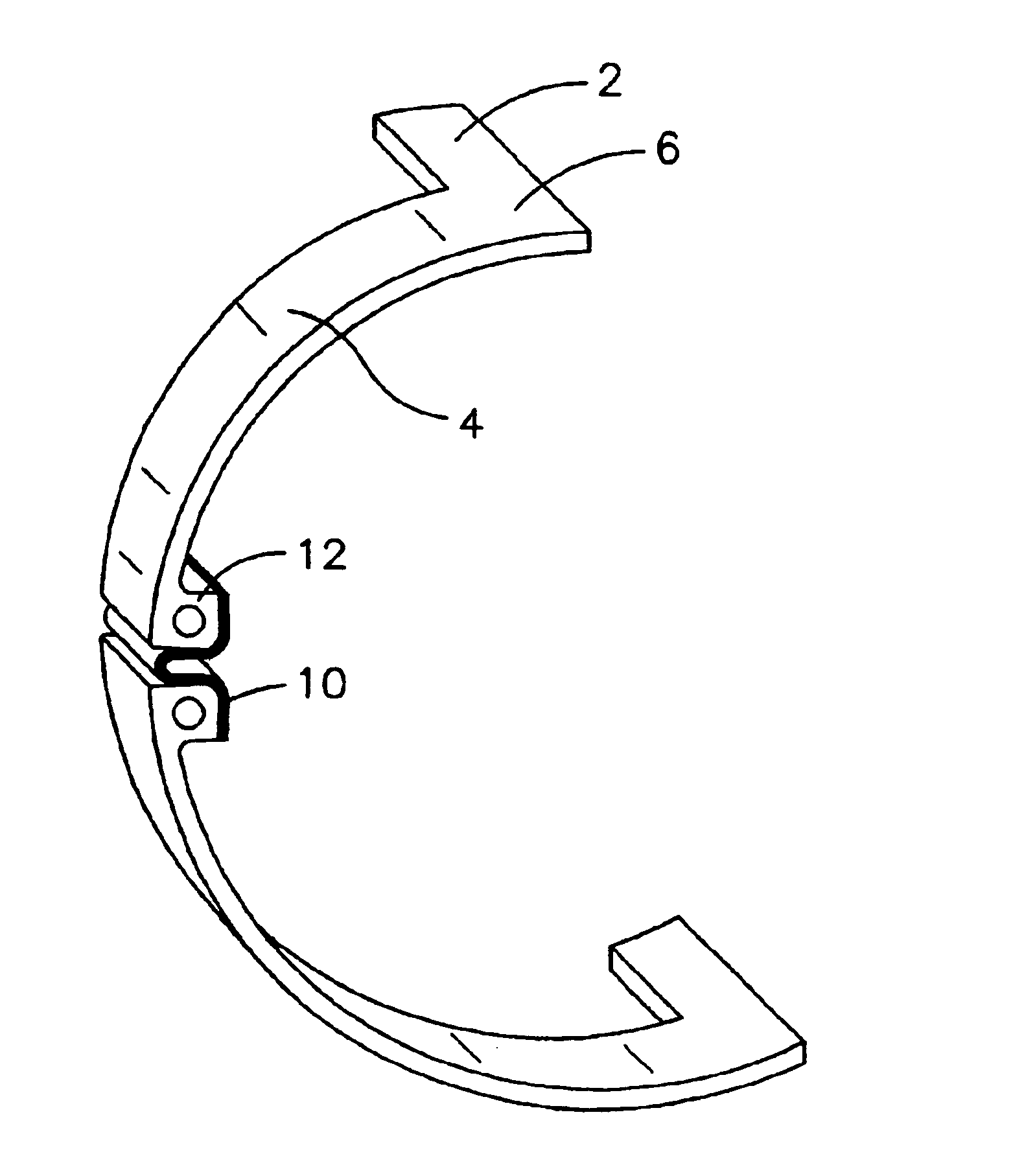
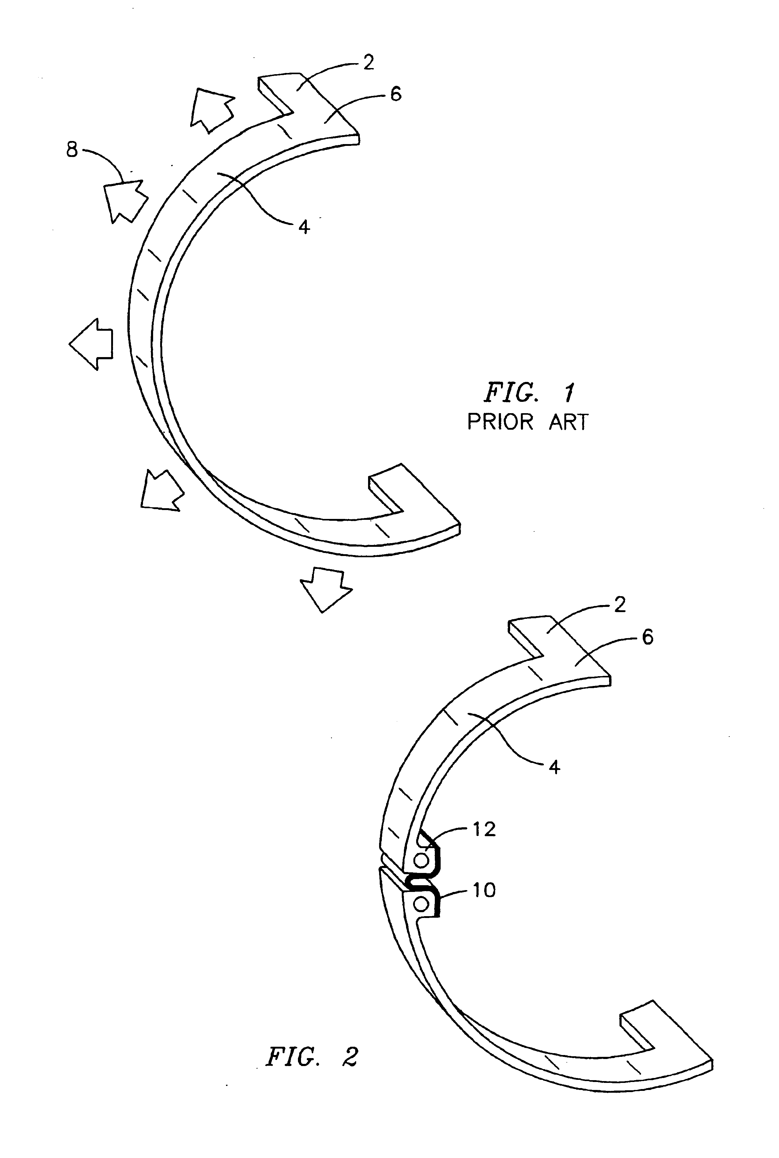
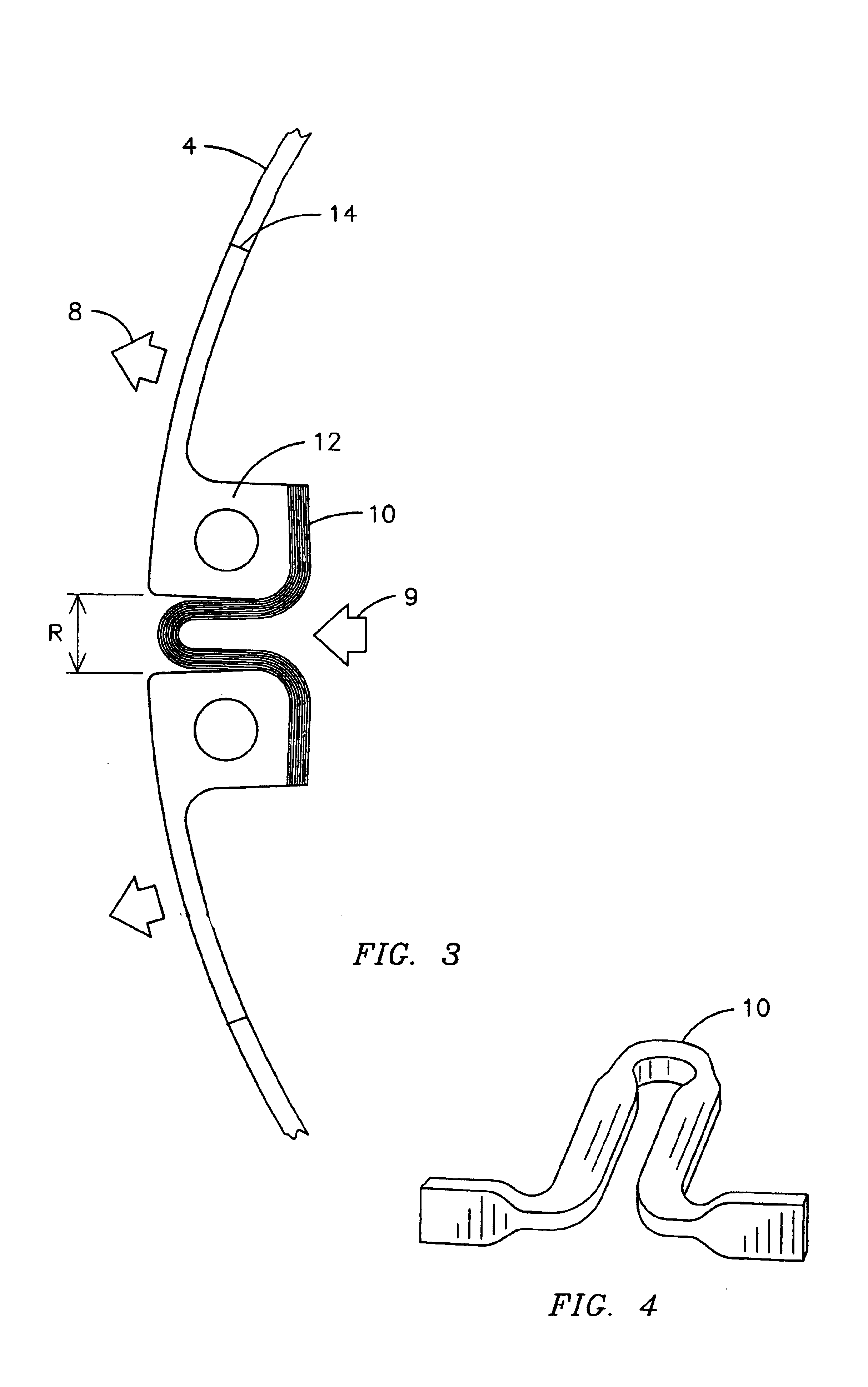
[0017]The present invention provides for a pole crossover with an inclusive area of expansion to relieve stress points on the crossover unit that would otherwise result from deflection during ordinary generator operation. Deflection of supporting elements causes the pole crossover to deflect in the outward radial direction and expand in the circumferential direction under the mechanical loading of rotational operation. However, this expansion puts strain where the circumferential band joins the axial arms that connect the band to the generator windings.

[0018]Since rotor generators are stopped and started daily, the expansion and contraction of the circumferential band puts repeated stress on the pole crossover joint, which is then subject to cracking and eventually electrical conductive failure. Therefore, it becomes necessary to inspect the pole crossover at regular intervals, and even to occasionally replace the pole crossover, which is very time consuming and risks damage to the ...


PUM


Abstract

The present invention increases the life of a pole crossover while minimizing the need for timely inspections and costly replacements. The present invention splits the pole crossover band 4 at one or more locations along its circumference and then joins the multiple arcs with a flexible member 10, such as an omega shaped bow. As deflection related stresses 8 increase, the circumference of the pole crossover band, the flexible member 10 allows for a natural expansion point in the otherwise rigid material. This relieves stresses that would otherwise be transferred to the connection point 6 between the pole crossover and the generator windings that can cause cracking and eventually generator failure.

Description

FIELD OF THE INVENTION[0001]The field of the invention relates to generator rotors, and specifically to current pole crossovers.BACKGROUND[0002]The pole windings of a generator rotor need to form a complete circuit and pole crossovers are used to this effect. Though pole crossovers can take the form of many different shapes and sizes, effectual pole crossovers for generator rotors are thick circular or semicircular bands of strong, highly conductive metal such as copper.[0003]FIG. 1 illustrates one type of semi-circular pole crossover. Axial arms 2 connect to either pole of the generator rotor winding and are joined together by a semi-circular band 4. Though not shown, the band abuts rotor windings on its outer circumference. The axial arms 2 proceed inboard into slots in the rotor forging body. The portions of the rotor winding outside of the rotor forging body are referred to as the rotor end windings. The axial arms 2 and band are joined, in this example, at square corners 6, whi...

Claims


Application Information

Patent Timeline
Patent Type & Authority Patents(United States)
IPC IPC(8): H02K3/12H02K3/52H02K3/46
CPCH02K3/12H02K3/527
Inventor SPENCER, CRAIG MICHAELWHITENER, RANDY ERICO, RAUL RZELLER, LARRY
Owner SIEMENS ENERGY INC
Why Eureka
Try Eureka