
Head coil arrays for parallel imaging in magnetic resonance imaging

a magnetic resonance imaging and parallel imaging technology, applied in the field of magnetic resonance imaging (mri) systems, can solve the problems of low signal-to-noise ratio (s/n), large coil, and inability to work well in coil systems for imaging deep tissues, and trade-off between basic noise and geometry factor

Inactive Publication Date: 2005-08-16
GENERAL ELECTRIC CO
View PDF14 Cites 43 Cited by
  • Summary
  • Abstract
  • Description
  • Claims
  • Application Information

AI Technical Summary

Problems solved by technology

A large coil, however, produces lower signal-to-noise ratio (S / N) if it is also used for reception, mainly because of its greater distance from the signal-generating tissues being imaged.
These coil systems do not work well for imaging deep tissues, such as the blood vessels in the lower abdomen, due to sensitivity drop-off away from the coil surface.
As stated in the above, the use of smaller coil-elements than those for conventional imaging results in a trade-off between basic noise and geometry factor.

Method used


Image

  • Head coil arrays for parallel imaging in magnetic resonance imaging
  • Head coil arrays for parallel imaging in magnetic resonance imaging
  • Head coil arrays for parallel imaging in magnetic resonance imaging

Examples


Embodiment Construction

[0038]As is seen from the equation above, we loose S / N intrinsically when we try to reduce the imaging time. Thus, to compensate for S / N loss, we design the size of each element smaller than that of conventional array elements. We also increase the total number of elements to cover the volume of interest (which may be constrained by the maximum available number of receiver channels).

[0039]The present invention provides an improved and advanced volume and surface coil array that covers a large field-of-view while providing greater S / N and can be used as a PPA targeted coil for imaging a large volume such as head, abdomen or heart.

[0040]The present invention may also employ various combinations of coils distributed not only in circumambient directions but also in the z direction and provide better S / N for the torso and cardiac imaging as compared with a conventional torso / cardiac coil.

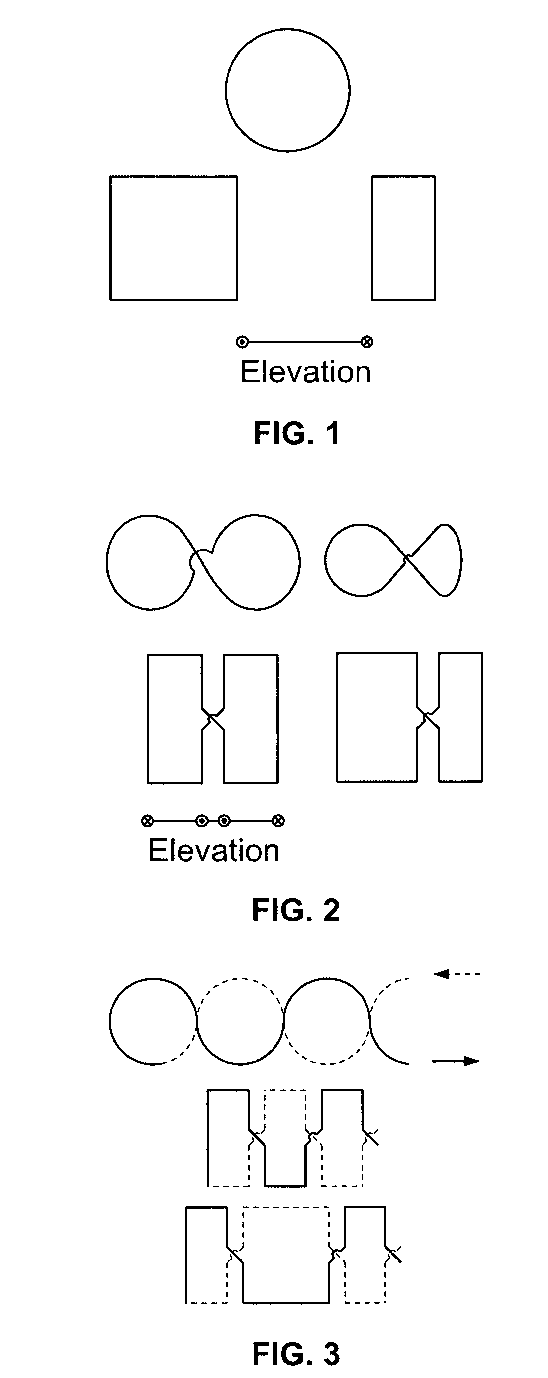
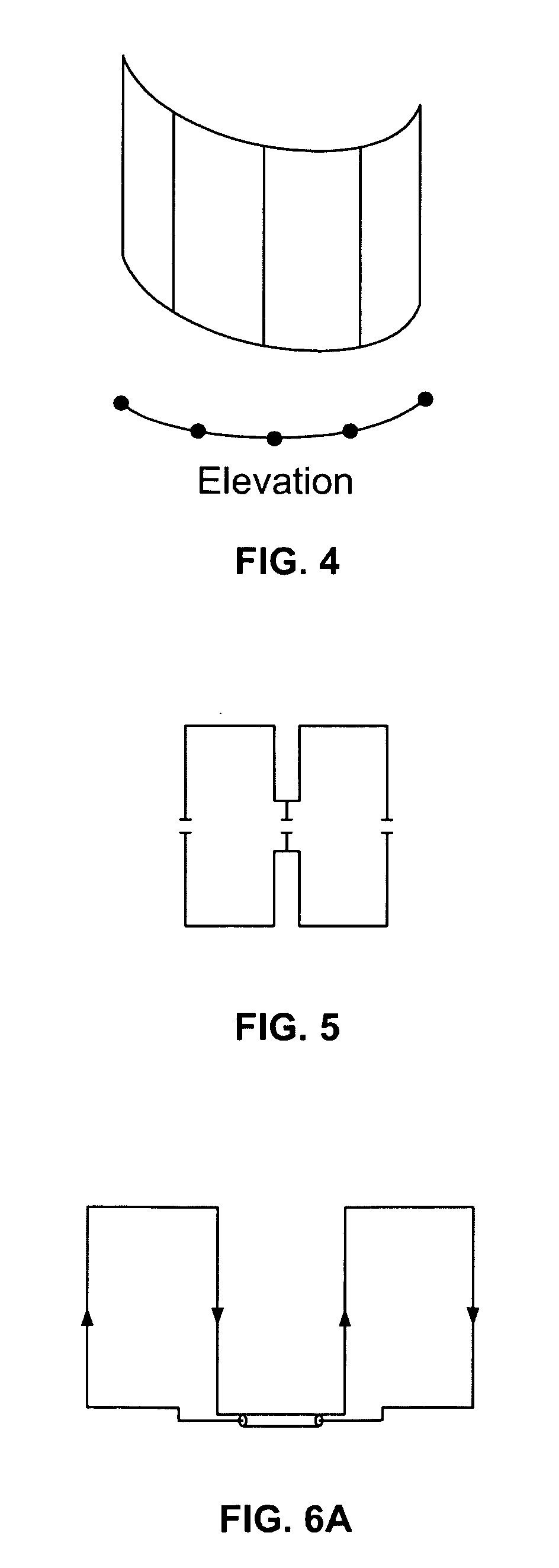
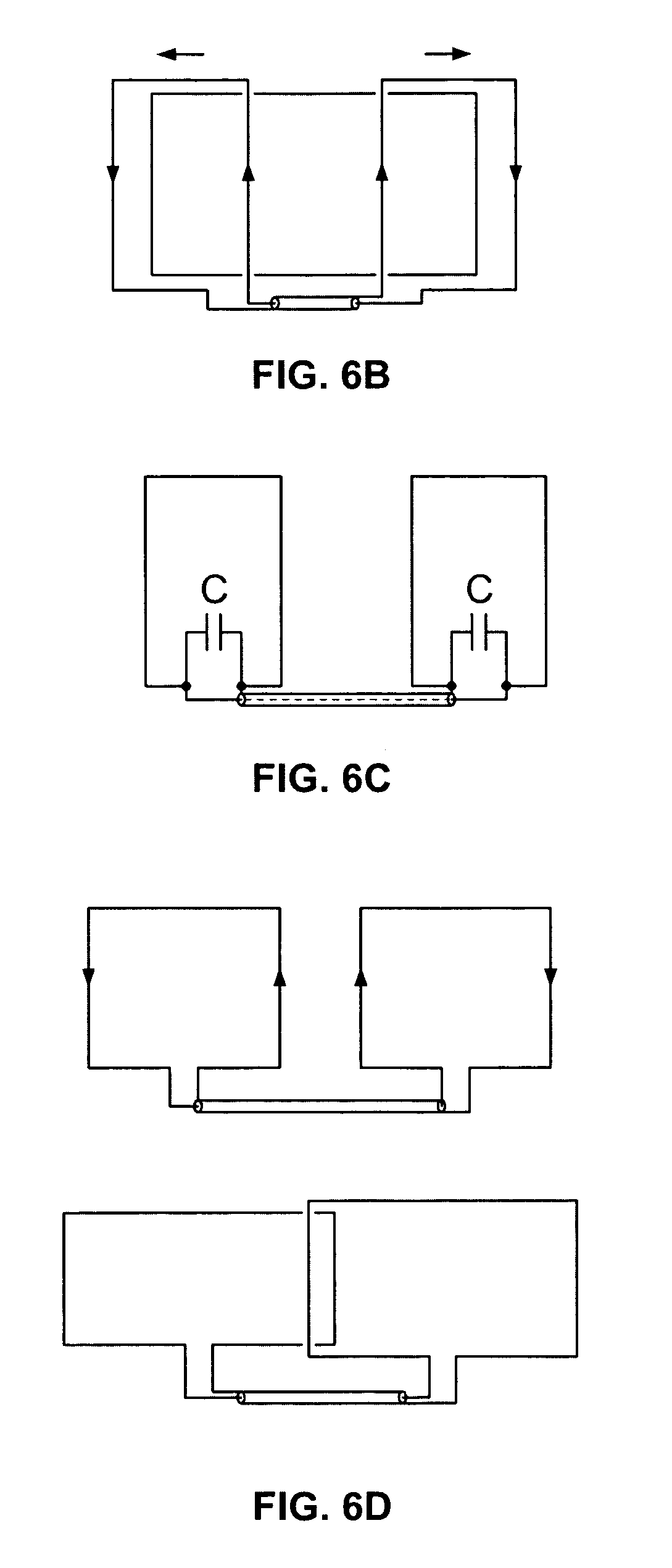
[0041]The basic building blocks of the present invention are the well-known coil configurations ofFIG...


PUM


Abstract

A partially parallel acquisition RF coil array for imaging a human head includes at least a first, a second and a third loop coil adapted to be arranged circumambiently about the lower portion of the head; and at least a forth, a fifth and a sixth coil adapted to be conformably arranged about the summit of the head. A partially parallel acquisition RF coil array for imaging a human head includes at least a first, a second, a third and a fourth loop coil adapted to be arranged circumambiently about the lower portion of the head; and at least a first and a second Figure-8 or saddle coil adapted to be conformably arranged about the summit of the head.

Description

CROSS-REFERENCE TO RELATED APPLICATION[0001]This application claims the benefit of U.S. provisional patent applications Ser. No. 60 / 302,158 filed Jun. 29, 2001 and Ser. No. 60 / 296,885 filed Jun. 8, 2001.[0002]This application is a continuation-in-part of U.S. utility patent application Ser. No. 10 / 164,664 filed Jun. 7, 2002.BACKGROUND OF THE INVENTION[0003]The present invention relates to magnetic resonance imaging (MRI) systems, and particularly to the radio frequency (RF) coils used in such systems.[0004]Magnetic resonance imaging (MRI) utilizes hydrogen nuclear spins of the water molecules in the human body or other tissue, which are polarized by a strong, uniform, static magnetic field generated by a magnet (referred to as B0— the main magnetic field in MRI physics). The magnetically polarized nuclear spins generate magnetic moments in the human body. The magnetic moments point in the direction of the main magnetic field in a steady state, and produce no useful information if th...

Claims


Application Information

Patent Timeline
Patent Type & Authority Patents(United States)
IPC IPC(8): G01R33/34G01R33/561G01R33/54
CPCG01R33/34046G01R33/5611
Inventor FUJITA, HIROYUKIPETROPOULOS, LABROS S.ZOU, MARK XUEMINGCHAN, PEI H.CHU, DASHENMURPHY-BOESCH, JOSEPH
Owner GENERAL ELECTRIC CO
Learn More