Digital camera apparatus with biometric capability

a biometric and digital camera technology, applied in the field of digital cameras and motion video, can solve the problems of not being able to recognize the vast potential of the information age and being difficult to obtain, and achieve the effect of greater ease of use and greater protection

Inactive Publication Date: 2005-08-16
MEDIATEK INC
View PDF7 Cites 130 Cited by
  • Summary
  • Abstract
  • Description
  • Claims
  • Application Information

AI Technical Summary

Benefits of technology

[0011]A digital camera as described herein provides an enhanced record supplementing its recorded digital images, provides

Problems solved by technology

Other information might be useful, but is not so easily obtained.
Most digital cameras to date have simply tried to mimic the capabilities of their mechanical device counterparts, making limited use of digital technologies other than simple optical scanning an

Method used


Image

  • Digital camera apparatus with biometric capability
  • Digital camera apparatus with biometric capability
  • Digital camera apparatus with biometric capability

Examples


first embodiment

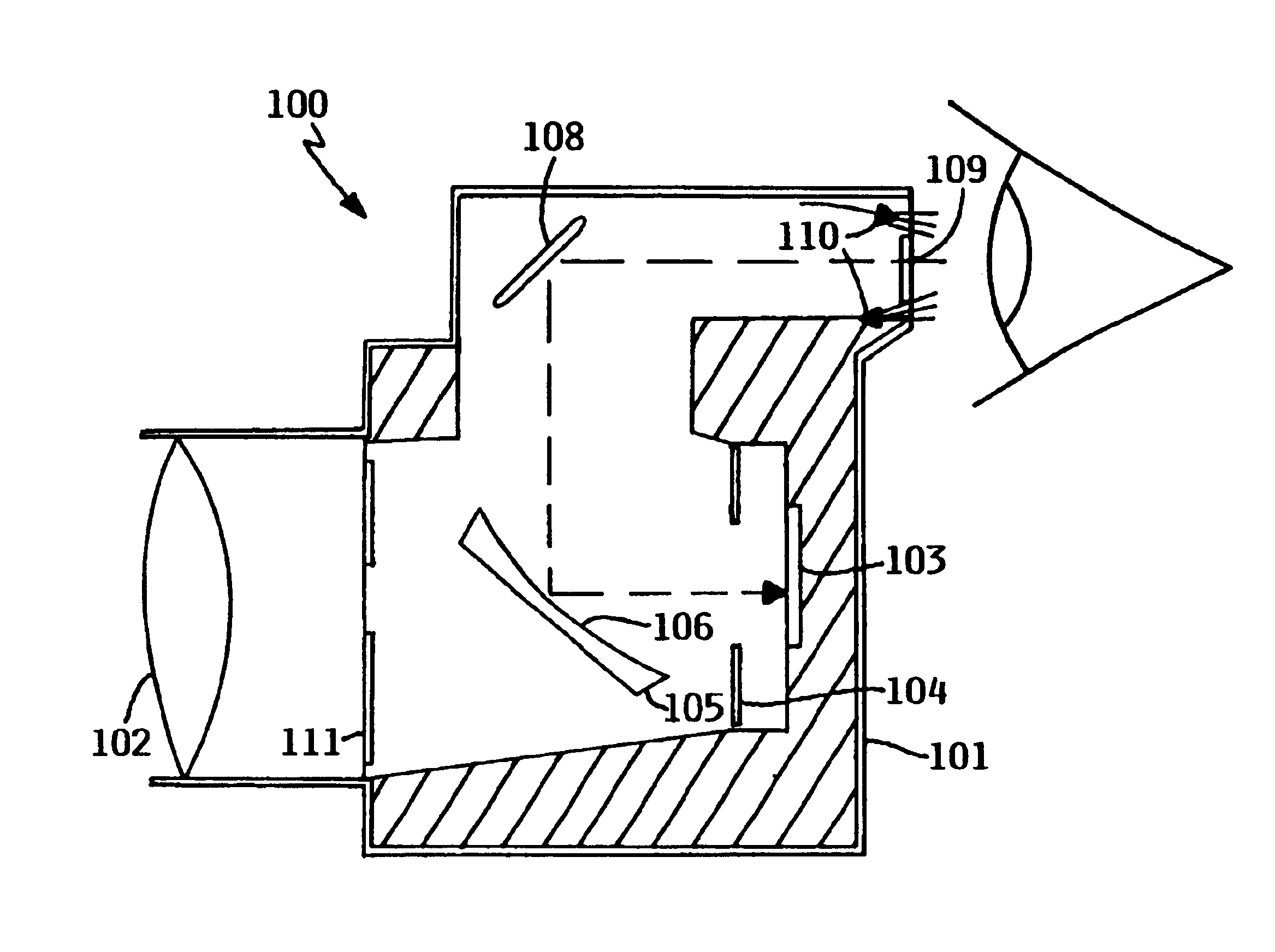
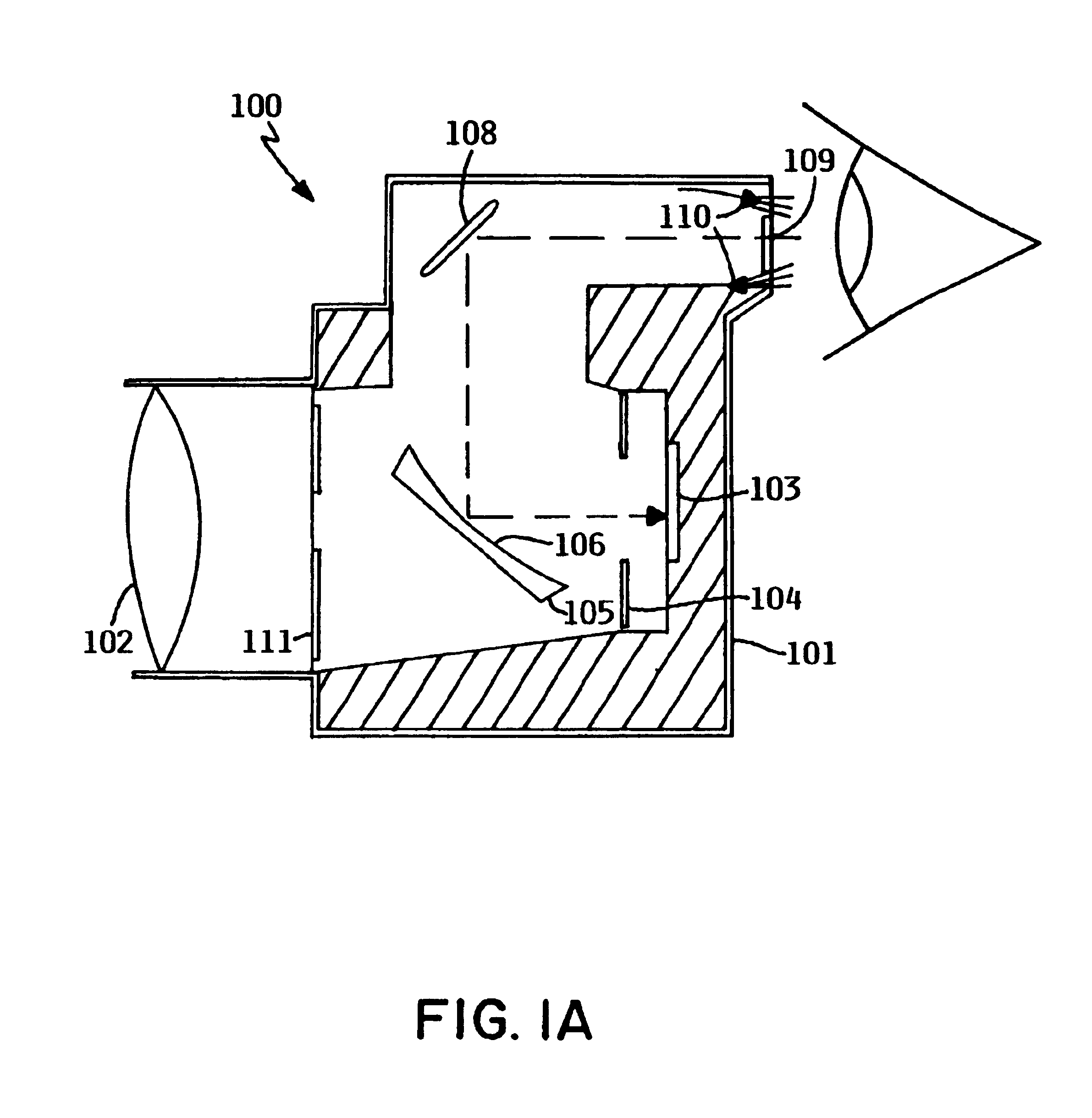
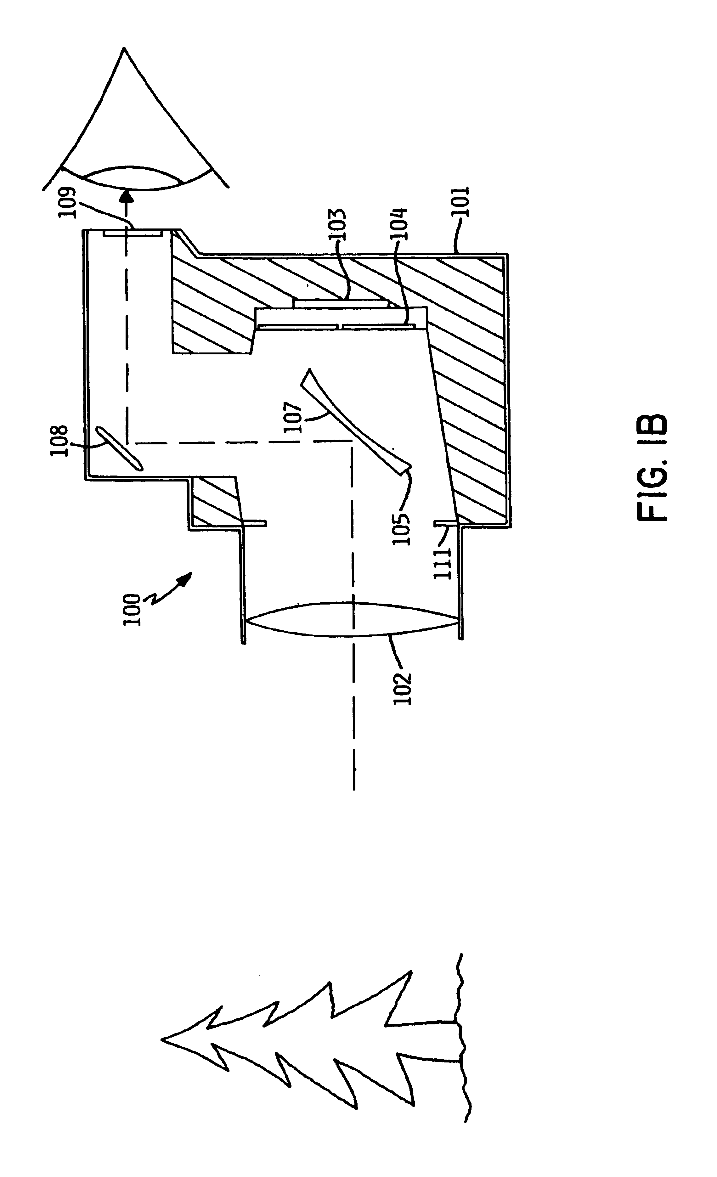
[0022]FIGS. 1A-1C are sectional views of different operational configurations of a digital camera according to a In this embodiment, camera 100 contains a single-lens-reflex (SLR) mechanism, wherein a single lens is used for both viewing an object of interest to be photographed, and for capturing light from the object on an optical sensor array. Camera 100 includes a body or housing 101, lens 102, optical sensor array 103, shutter 104, and deflection mirror 105. FIG. 1B shows the configuration of camera 100 when the photographer is viewing the object of interest, represented as a tree, which is generally done to establish the correct setting prior to taking the photograph. In this configuration, shutter 104 is closed, and deflection mirror 105 presents surface 107 (usually a flat surface) at an angle to incoming light passing through lens 102. Light is deflected upwards, striking mirror 108, which directs it through view window 109 to the eye of the photographer. As depicted in FIG...

second embodiment

[0025]FIGS. 2A and 2B are sectional views representing different operational configurations of a digital camera according to a In this embodiment, a viewing window is separated from the image capturing portion of the camera, so that the photographer views the object of interest through a separate light path which does not pass through the photographing lens. Camera 200 comprises housing 201, lens 202, optical sensor array 203, and shutter 204. FIG. 2B shows a configuration of camera 200 during capture of a photograph. Shutter 204 is open, and light from the object of interest passes through lens 202 and registers on sensor array 203. Concurrently, the photographer may view the object of interest through a pair of viewing windows 207 and 208. During set-up of the photograph, the configuration is identical to that shown in FIG. 2B, except that shutter 204 is closed.

[0026]FIG. 2A shows a configuration of camera 200 during registration of the photographer's iris. At this time, shutter ...

third embodiment

[0027]FIG. 3 is a sectional view of a digital camera according to a In this embodiment, there is no direct light path from the object of interest to the photographer; instead, a small display within the camera regenerates the image that is sensed by the optical sensor array, for display to the photographer. As shown in FIG. 3, camera 300 contains a housing 301, lens 302, optical sensor array 303, and shutter 304. Light from an object of interest passes through lens 302, which focuses it on sensor array 303. The detection electronics within the camera then cause the image detected by sensor array 303 to be displayed on display 308, which may be a liquid crystal or other appropriate display. The photographer views this display to determine what the camera is sensing and set up the photograph.

[0028]One-way mirror glass 306 mounted at an oblique angle to display 308 permits light from display 308 to pass through glass 306 and view window 309 to the photographer's eye. View window 309 m...


PUM


Abstract

A digital camera contains biometric capability to identify a photographer, which is preferably provided by the camera's own optical sensors. The biometric feature is preferably the iris of a photographer's eye, which is recognized as unique for each individual. The camera captures an image of an iris, abstracts a set of distinguishing features, and matches this set to an on-board database. The iris image is preferably captured when the photographer brings his eye in the vicinity of the camera's viewing window, through a combination of mirrors, lenses, prisms, and the like. This capability may be used to record the identity of a photographer with the image, as an anti-theft or privacy device, or to personalize the camera settings.

Description

FIELD OF THE INVENTION[0001]The present invention relates to digital data devices, and in particular to digital cameras, motion video, and similar devices which digitally capture optical images.BACKGROUND OF THE INVENTION[0002]The latter half of the twentieth century has been witness to a phenomenon known as the information revolution. While the information revolution is a historical development broader in scope than any one event or machine, no single device has come to represent the information revolution more than the digital electronic computer. The development of computer systems has surely been a revolution. Each year, computer systems grow faster, store more data, and provide more applications to their users.[0003]The declining prices and expanding capabilities of modem digital technology has caused it to be used in an ever increasing variety of applications. One of these applications has been the capturing of optical images. Optical imaging technology generally uses a digita...

Claims


Application Information

Patent Timeline
IPC IPC(8): G06K9/00H04N5/232
CPCG06K9/00597H04N5/232G06V40/18
Inventor BATES, CARY LEEBARSNESS, ERIC LAWRENCESANTOSUOSSO, JOHN MATTHEW
Owner MEDIATEK INC
Why Eureka
Try Eureka