
Method and apparatus for exposing a latent watermark on film

a technology of imaging film and watermark, applied in the field of providing watermarks on imaging film mediums, can solve the problems of affecting the image quality, and affecting the overall film viewing experience, so as to simplify the design complexity and cost, reduce the impact of visible watermarks, and achieve sufficient speed

Inactive Publication Date: 2005-08-16
EASTMAN KODAK CO
View PDF14 Cites 19 Cited by
  • Summary
  • Abstract
  • Description
  • Claims
  • Application Information

AI Technical Summary

Benefits of technology

The present invention provides an apparatus and method for adding a spatially sparse watermark onto a newly manufactured photosensitive film, such as motion picture film. The apparatus uses a combination of spatial light modulators to create a latent image of modulated stripes with a predetermined intensity. The watermark is formed by alternating exposure patterns from two spatial light modulators, resulting in a seamless watermark that is imperceptible to viewers. The apparatus and method can be used in high-speed film finishing operations and are tolerant to alignment differences between the spatial light modulators. The watermark can be formed without altering existing timing or sequencing operations and does not require expensive positional tracking mechanisms. The watermark is relatively imperceptible to viewers and can be used with low-cost spatial light modulators.

Problems solved by technology

A visible watermark would be annoying and would detract from image quality and from the overall film viewing experience.(b) Robust.
There would be considerable reluctance among film manufacturers or processors to adapting a watermarking method that slowed motion film production or processing.(e) Ease of integration.
film. While the disclosed apparatus can provide accurate color-neutral exposure onto stationary film as part of a manufacturing test process, its power is not sufficient for exposing film that is traveling at speeds in excess of a few feet / s
econd. Moreover, resolution provided by this technique is not sufficient for minimizing the visible effects of the embedded data.< / l
However, none of the approaches outlined in these disclosures is well suited for motion picture film watermarking, in light of the requirements listed in (a) through (e) above.
As is noted above, changes to the existing, high-volume workflow are not likely to gain acceptance.
With film moving through fabrication stages at high speeds, extremely high intensity and very short exposure times are required.
Reciprocity failure problems in film exposure, heightened by these requirements, further complicate the problem of applying a two-dimensional watermark.
Thus, it can be seen that the prior art solutions noted above are not well suited to the requirement for pre-exposure of a watermark following high-speed film coating and drying and preceding high-volume packaging operations.
Further, considering the needed response and refresh times, most types of image-forming devices simply operate too slowly for high-speed watermarking applications.

Method used


Image

  • Method and apparatus for exposing a latent watermark on film
  • Method and apparatus for exposing a latent watermark on film
  • Method and apparatus for exposing a latent watermark on film

Examples


Embodiment Construction

[0066]The present invention is directed in particular to elements forming part of, or in cooperation more directly with an apparatus in accordance with the present invention. It is to be understood that elements not specifically shown or described may take various forms well known to those skilled in the art.

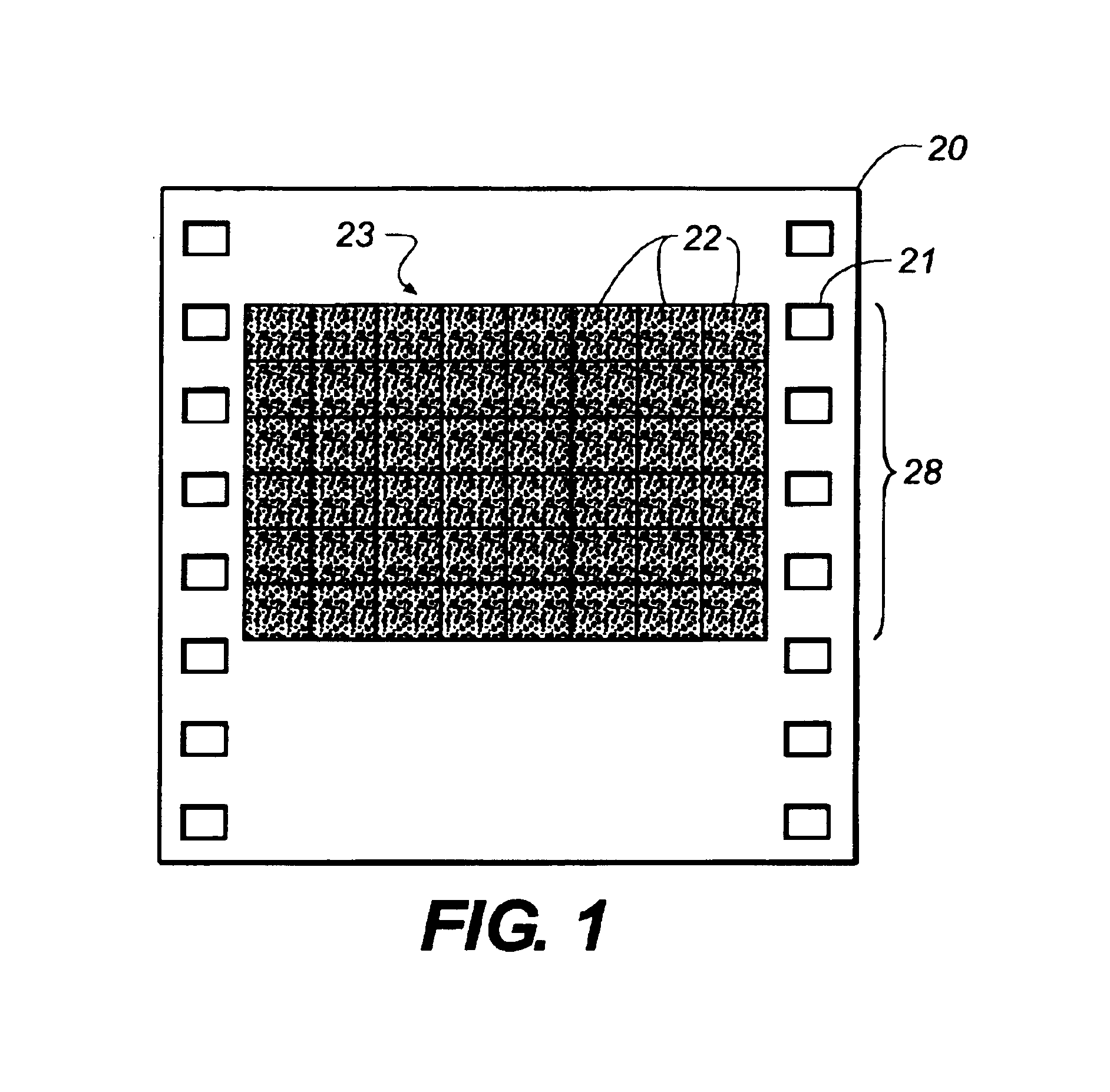
[0067]Referring to FIG. 1, there is shown a conventional area coverage watermark 23 within an image frame 28. A film 20 has perforations (perfs) 21, where a typical image frame, including the interframe gap, covers four perfs. Area watermark 23 consists of an 8×6 array of identical tiles 22, each tile 22 is repeated multiple times within image frame 28. An array of tiles 22 covers the full aperture of image frame 28 and also covers any gap between image frames 28. Entire area watermark 23 of 8×6 tiles 22 may be exposed simultaneously or may be formed by exposing a single row of tiles 22 at a time. Using such a method, after exposure of a row of tiles 22, film 20 is transported t...


PUM


Abstract

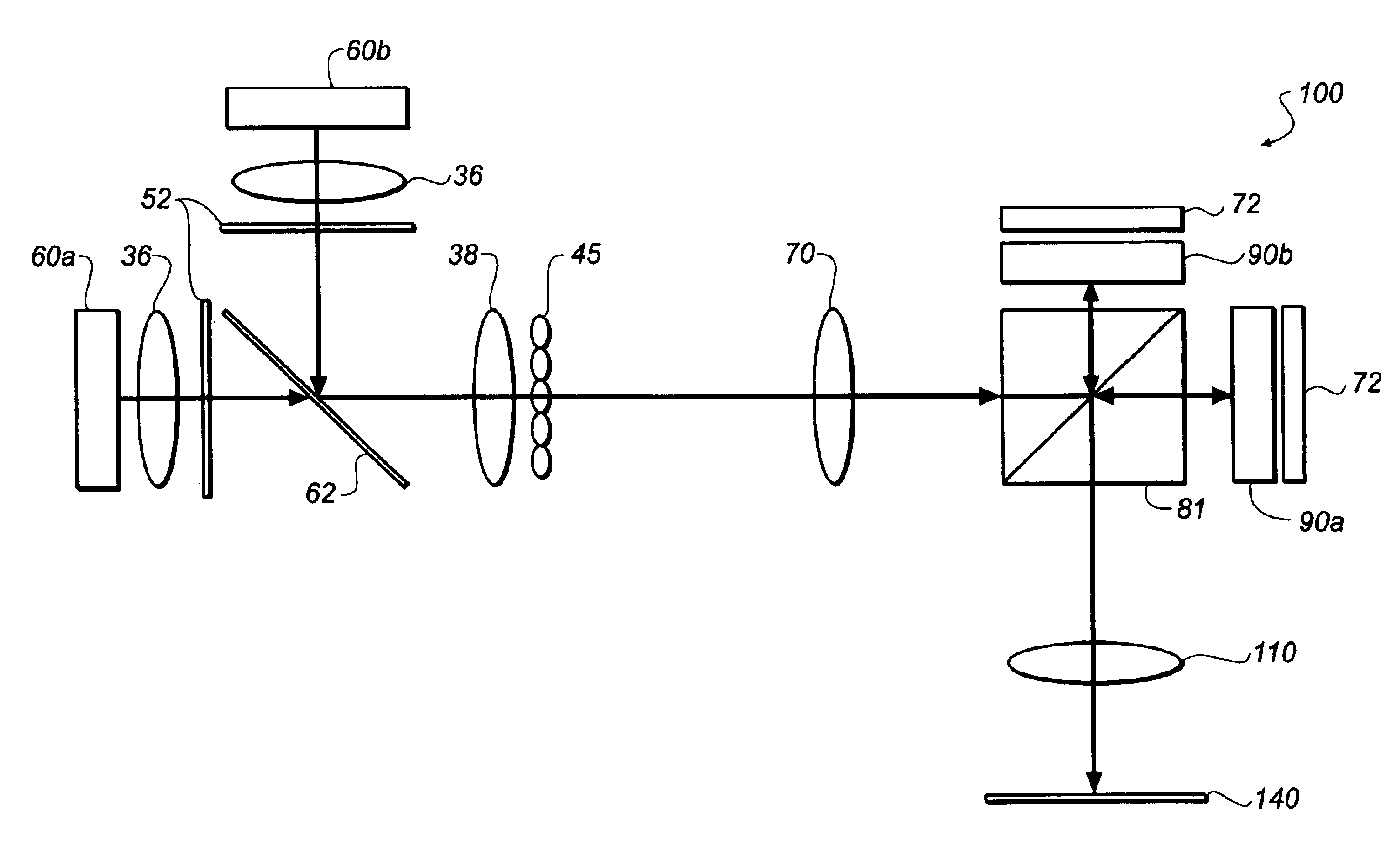
A printing method and apparatus (100) for pre-exposing a digital watermark along a length of photosensitive medium at the time of manufacture is disclosed. The printing apparatus has an illumination source (60) for providing an exposure illumination, first and second LCD spatial light modulators (90a, 90b) for modulating the exposure illumination to form first and second exposure patterns according to image data, combining optics providing a single output path for directing both first and second exposure patterns onto the photosensitive medium and transport means for providing, during exposure, lengthwise displacement of the photosensitive medium with respect to the output path. The first and second exposure patterns form, lengthwise along the photosensitive medium, a latent image with modulated stripes having a predetermined intensity corresponding to the exposure patterns.

Description

CROSS REFERENCE TO RELATED APPLICATIONS[0001]Reference is made to commonly-assigned copending U.S. patent application Ser. No. 10 / 342,009, filed Jan. 14, 2003, entitled IMPROVED LIGHT SOURCE USING LARGE AREA LEDs, by Oehlbeck et al., and U.S. patent application Ser. No. 10 / 364,488, filed Feb. 11, 2003, entitled METHOD AND APPARATUS FOR WATERMARKING FILM, by Roddy et al., the disclosures of which are incorporated herein.FIELD OF THE INVENTION[0002]This invention relates to providing a watermark on an imaging film medium in general, and in particular relates to forming a watermark onto photosensitive film that is manufactured at high speeds, such as motion picture film.BACKGROUND OF THE INVENTION[0003]An encoded watermark is one type of forensic aid that has been proposed for identifying the source of an illegal copy of a motion picture. When provided with a suitable watermark, a projected motion picture image carries within itself identifying data that persists after any type of copy...

Claims


Application Information

Patent Timeline
Patent Type & Authority Patents(United States)
IPC IPC(8): G03B27/54G03B17/24G03B27/52
CPCG03B17/245G03B27/521G03B27/547
Inventor RODDY, JAMES E.ZOLLA, ROBERT J.HORVATH, LOUIS S.
Owner EASTMAN KODAK CO
Learn More