Radio equipment capable of real time change of antenna directivity and doppler frequency estimating circuit used for the radio equipment

a radio equipment and directivity technology, applied in the direction of substation equipment, spatial transmit diversity, multi-antenna systems, etc., can solve the problems of affecting the communication of regular users, requiring a complicated process, and reducing transmission directivity, so as to achieve satisfactory control of transmission directivity and correct estimation of transmission response vectors

Inactive Publication Date: 2005-08-16
KYOCERA CORP
View PDF13 Cites 11 Cited by
  • Summary
  • Abstract
  • Description
  • Claims
  • Application Information

AI Technical Summary

Benefits of technology

[0060]An object of the present invention is to provide a radio equipment capable of correctly estimating a transmission response vector of the down link even when there is an estimation error in the reception response vector estimated for the up link, and hence capable of satisfactory control of transmission directivity.

Problems solved by technology

In this case, it follows that the adaptive array radio base station 1 receiving the mixed radio signals from both users A and B in the aforementioned manner outputs the signals from the users A and B in a mixed state unless some necessary processing is performed, to disadvantageously hinder communication with the regular user A.
It requires, however, a complicated process.
Therefore, if the speed of movement of the user terminal is not negligible, transmission directivity degrades because of the difference between the direction of radiowave emission from the base station and the actual direction of the user terminal.
When there is an estimation error in the reception response vector estimated for the up link because of a noise in the reception signal or sampling error, there would be an error in the result of extrapolation, making it difficult to correctly estimate the transmission response vector for the down link, and hence, it becomes impossible to realize satisfactory control of transmission directivity.
More specifically, dependent on the degree of fading on the propagation path, there would be an error in the result of extrapolation.
In the conventional method, however, the correlation value is calculated using reference signals that are included in the reception signals themselves, which means that there are much interfering components, making correct estimation difficult.
Therefore, it was impossible to calculate the correlation value at an arbitrarily timing, and therefore, the calculating process was not flexible.
Meanwhile, the method of estimating Doppler frequency of the propagation path for each user terminal separated by the adaptive array processing has not yet been developed.

Method used


Image

  • Radio equipment capable of real time change of antenna directivity and doppler frequency estimating circuit used for the radio equipment
  • Radio equipment capable of real time change of antenna directivity and doppler frequency estimating circuit used for the radio equipment
  • Radio equipment capable of real time change of antenna directivity and doppler frequency estimating circuit used for the radio equipment

Examples


Embodiment Construction

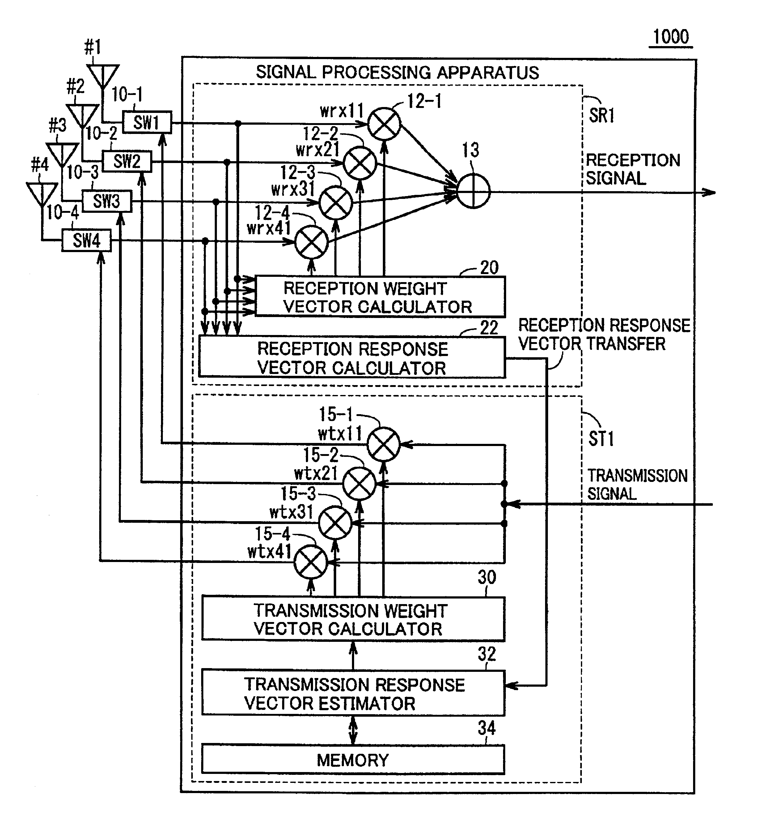
[0129]FIG. 1 is a schematic block diagram representing a radio equipment (radio base station) 1000 of a PDMA base station in accordance with an embodiment of the present invention.

[0130]In the configuration shown in FIG. 1, in order to distinguish a user PS1 from a user PS2, four antennas #1 to #4 are provided. The number of antennas, however, may be generally represented as N (N: natural number).

[0131]In the transmission / reception system 1000 shown in FIG. 1, a reception unit SR1 receiving signals from antennas #1 to #4 and separating a signal from a corresponding user (for example, user PS1), and a transmitting unit ST1 for transmitting a signal to user PS1 are provided. Connection between antennas #1 to #4 and reception unit SR1 or transmission unit ST1 is selectively switched by switches 10-1 to 10-4.

[0132]More specifically, reception signals RX1(t), RX2(t), RX3(t) and RX4(t) received by respective antennas are input to reception unit SR1 through corresponding switches 10-1, 10-...


PUM


Abstract

A radio equipment separates a signal from a specific terminal among signals from adaptive array antennas, based on a reception weight vector calculated by a reception weight vector calculator. A reception response vector calculator draws out a reception response vector of a propagation path of the signal from the specific terminal. A correlation operation and Doppler frequency estimating circuit calculates a correlation value between reception response vectors of corresponding slots of continuous frames, and estimates a corresponding Doppler frequency based on a correspondence found in advance. A transmission response vector estimator predicts a transmission response vector, by performing an extrapolation process in accordance with the estimated Doppler frequency.

Description

BACKGROUND OF THE INVENTION[0001]1. Field of the Invention[0002]The present invention relates to a radio equipment that can change antenna directivity on real time basis as well as to a Doppler frequency estimating circuit used therefor. More specifically, the present invention relates to a radio equipment used in an adaptive array radio base station, and to a Doppler frequency estimating circuit used therefor.[0003]2. Description of the Background Art[0004]Recently, various methods of transmission channel allocation have been proposed to realize effective use of frequency, in a mobile communication system, of which some have been practically implemented.[0005]FIG. 15 shows an arrangement of channels in various communication systems including frequency division multiple access (FDMA), time division multiple access (TDMA) and path division multiple access (PDMA).[0006]Referring to FIG. 15, FDMA, TDMA and PDMA will be briefly described. FIG. 15(A) represents FDMA in which analog signa...

Claims


Application Information

Patent Timeline
Patent Type & Authority Patents(United States)
IPC IPC(8): H04B7/01H04B7/04H04B7/08H04B7/06H04B7/26
CPCH04B7/01H04B7/0615H04B7/0617H04B7/0848H04B7/0854H04B7/26
Inventor KITAKADO, JUNDOI, YOSHIHARU
Owner KYOCERA CORP
Why Eureka
Try Eureka