Rotating pulse detonation system for a gas turbine engine

a gas turbine engine and pulse detonation technology, which is applied in the ignition of the turbine/propulsion engine, intermittent jet plants, lighting and heating apparatus, etc., can solve the problems of increasing the cost of further improvements, the valve and associated actuators are subjected to very high temperatures and pressures, and the reliability problem

Inactive Publication Date: 2005-08-23
GENERAL ELECTRIC CO
View PDF10 Cites 22 Cited by
  • Summary
  • Abstract
  • Description
  • Claims
  • Application Information

AI Technical Summary

Problems solved by technology

While engines based on the Brayton Cycle have reached a high level of thermodynamic efficiency by steady improvements in component efficiencies and increases in pressure ratio and peak temperature, further improvements are becoming increasingly costly to obtain.
While such pulse detonation configurations have advanced the state of the art, the valves and associated actuators are subjected to very high temperatures and pressures.
This not only presents a reliability problem, but can also have a detrimental effect on the turbomachinery of the engine.

Method used


Image

  • Rotating pulse detonation system for a gas turbine engine
  • Rotating pulse detonation system for a gas turbine engine
  • Rotating pulse detonation system for a gas turbine engine

Examples


Embodiment Construction

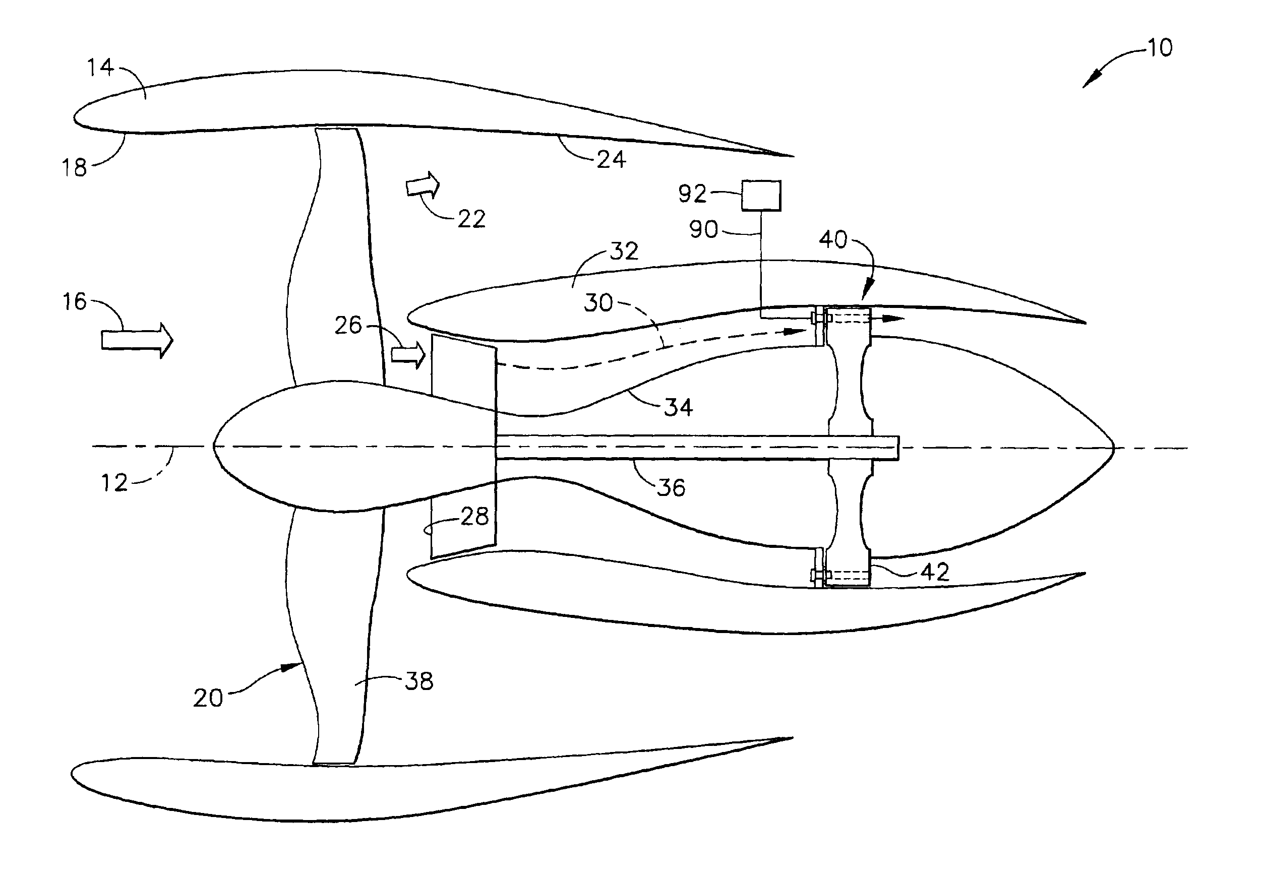
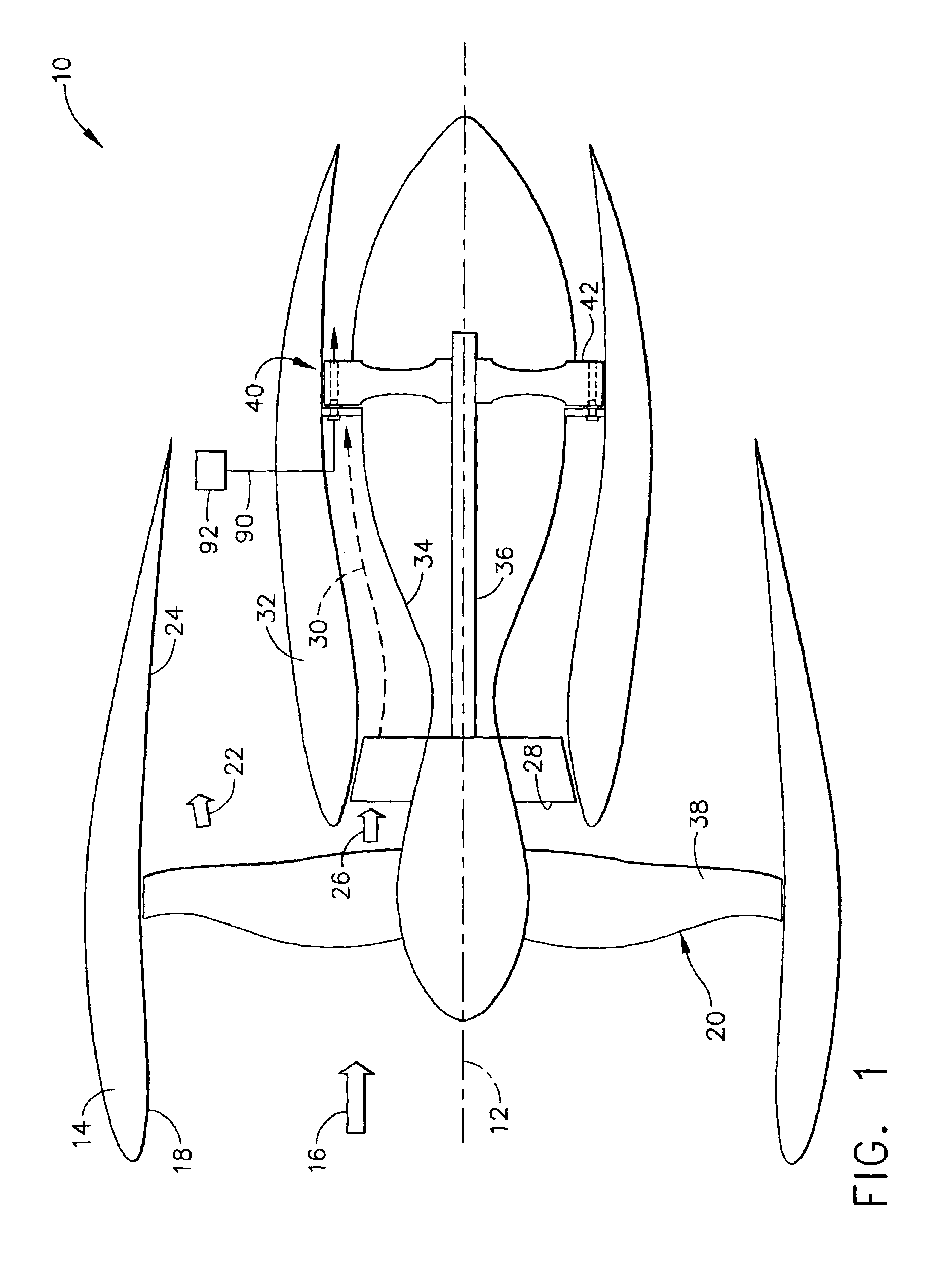
[0029]Referring now to the drawings in detail, wherein identical numerals indicate the same elements throughout the figures, FIG. 1 schematically depicts an exemplary gas turbine engine 10 (high bypass type) utilized with aircraft having a longitudinal or axial centerline axis 12 therethrough for reference purposes. Gas turbine engine 10 includes a nacelle 14 to assist in directing a flow of air (represented by arrow 16) through an inlet 18 to a fan section 20 as is well known. Air flow 16 is then split downstream of fan section 20 so that a first portion (represented by arrow 22) flows through an outer duct 24 and a second portion (represented by arrow 26) is provided to a booster compressor 28.

[0030]In the high bypass configuration depicted, it will be understood that booster compressor 28 preferably provides a compressed air flow 30 which is bounded by an inner bypass platform 32 and a gooseneck inner flow path 34. It will be noted that booster compressor 28 preferably includes a...


PUM


Abstract

A pulse detonation system for a gas turbine engine having a longitudinal centerline axis extending therethrough includes a rotatable cylindrical member having a forward surface, an aft surface, and an outer circumferential surface, where a plurality of spaced detonation passages are disposed therethrough. Each detonation passage includes at least a portion having a longitudinal axis extending therethrough oriented at a circumferential angle to the longitudinal centerline axis. The pulse detonation system further includes a shaft rotatably connected to the cylindrical member and a stator configured in spaced arrangement with the forward surface of the cylindrical member and a portion of the shaft. The stator has at least one group of ports formed therein alignable with the detonation passages as the cylindrical member rotates. In this way, detonation cycles are performed in the detonation passages so that combustion gases exit the aft surface of the cylindrical member to create a torque which causes the cylindrical member to rotate. Each detonation passage further includes a first end located adjacent the forward surface of the cylindrical member and a second end located adjacent the aft surface of the cylindrical member.

Description

BACKGROUND OF THE INVENTION[0001]The present invention relates generally to a pulse detonation system for a gas turbine engine and, in particular, to a pulse detonation system which is able to replace the core of a gas turbine engine without use of an externally actuated valve system.[0002]It is well known that typical gas turbine engines are based on the Brayton Cycle, where air is compressed adiabatically, heat is added at constant pressure, the resulting hot gas is expanded in a turbine, and heat is rejected at constant pressure. The energy above that required to drive the compression system is then available for propulsion or other work. Such gas turbine engines generally rely upon deflagrative combustion to burn a fuel / air mixture and produce combustion gas products which travel at relatively slow rates and constant pressure within a combustion chamber. While engines based on the Brayton Cycle have reached a high level of thermodynamic efficiency by steady improvements in compo...

Claims


Application Information

Patent Timeline
Patent Type & Authority Patents(United States)
IPC IPC(8): F02C5/04F02K3/06F02K7/06F02K7/075F02C5/11F02C5/12F02K7/00F02C5/00F02K3/00F23R7/00
CPCF02C5/11F02C5/12F02K3/06F23R7/00F05D2250/314F02K7/02
Inventor VENKATARAMANI, KATTALAICHERI SRINIVASANBUTLER, LAWRENCELEE, CHING-PANGMACLIN, HARVEY MICHAEL
Owner GENERAL ELECTRIC CO
Why Eureka
Try Eureka