

Viscometer sag test shoe
- Summary
- Abstract
- Description
- Claims
- Application Information
AI Technical Summary
Benefits of technology
Problems solved by technology
Method used
Image

Examples
Embodiment Construction
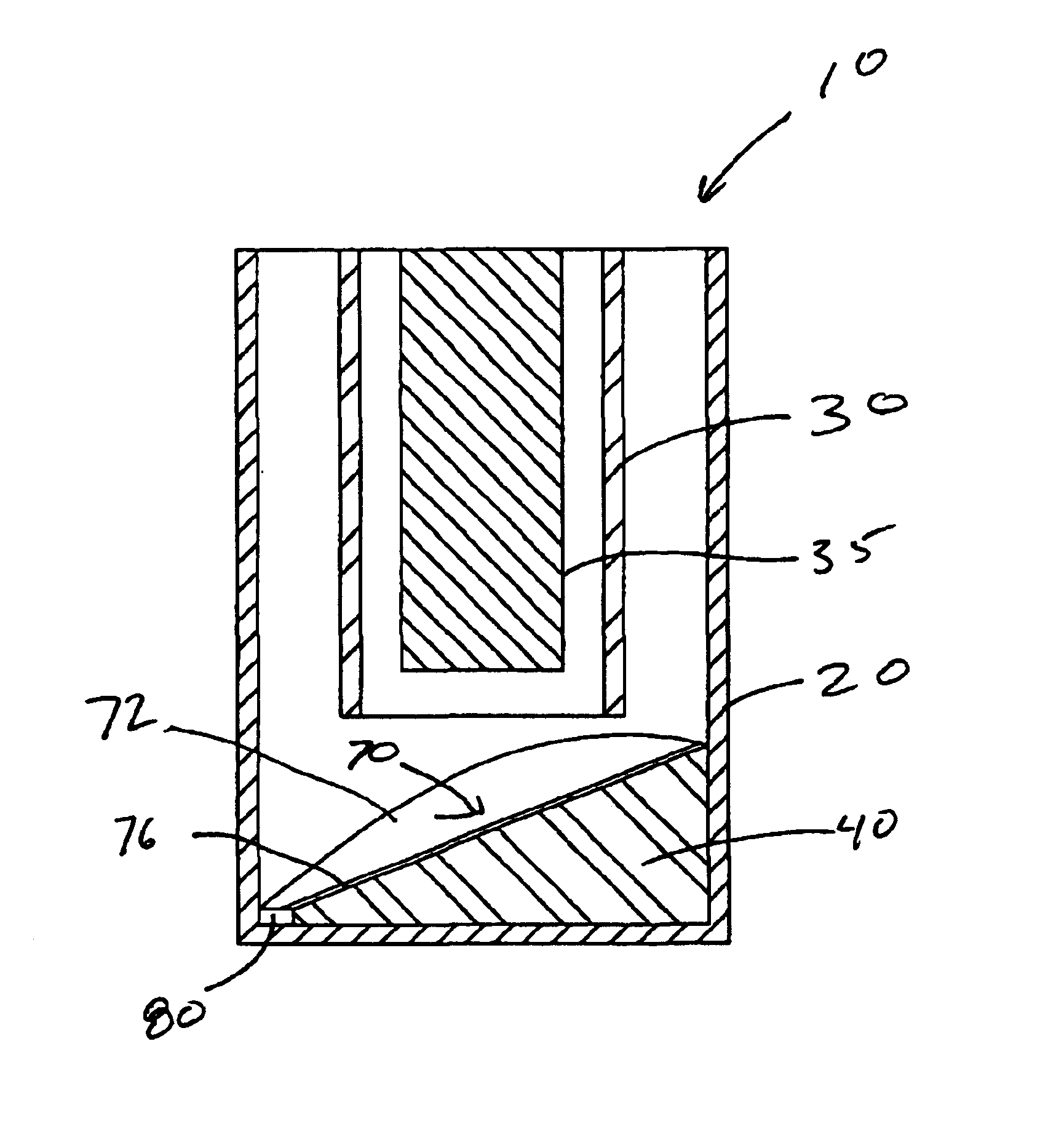
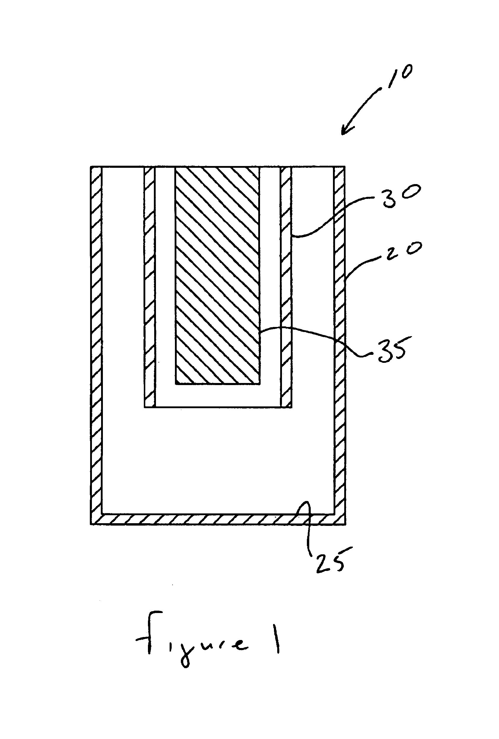
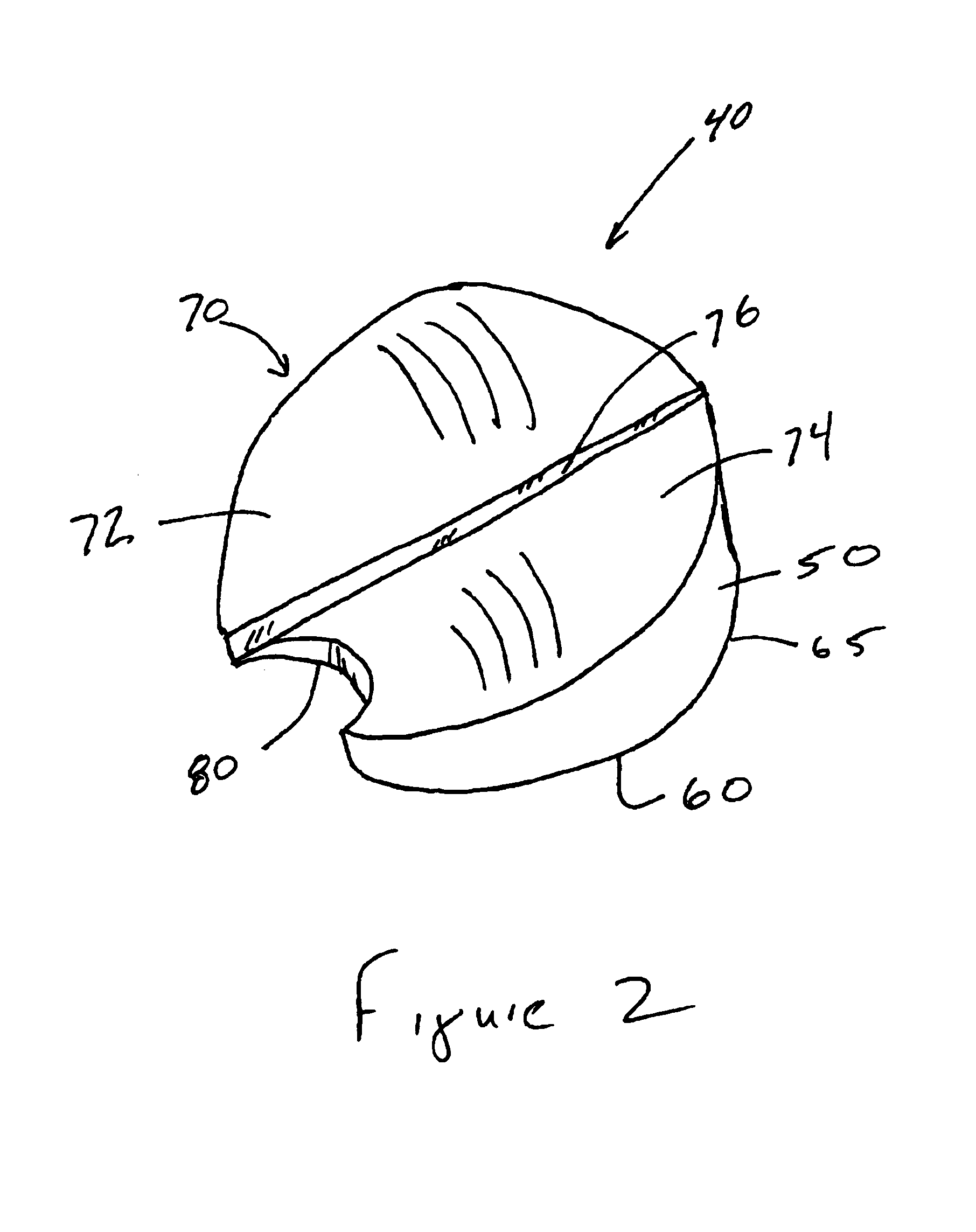
[0013]Accordingly, there are provided herein methods and apparatus for measuring sag properties of a drilling fluid using a rotary viscometer. An insert, or shoe, is placed at the bottom of the heat cup containing the fluid to be tested. A rotating cylinder is disposed within the fluid and solid particles are allowed to settle toward the bottom of the heat cup. The shoe incorporates a curved and inclined upper surface that directs the settled particles toward a well located at or near the outer edge of the shoe. As the test is performed, fluid samples can be withdrawn from the well and analyzed. If appropriate, the samples can then be returned to the well and the test continued. The insert concentrates the settled solids into a single location, which increases the sensitivity of the test and provides a location for sample acquisition that is easily and repeatedly located, which allows for improved correlation with laboratory and flow loop results.
[0014]In one embodiment, an assembly...
PUM
| Property | Measurement | Unit |
|---|---|---|
| Time | aaaaa | aaaaa |
Abstract
Description
Claims
Application Information