Acoustic control of the composition and/or volume of fluid in a reservoir

a technology of composition and/or volume, applied in the direction of valve details, burettes/pipettes, large containers, etc., can solve the problems of reducing compromising the fluid transport performance, and affecting the flow rate of fluid,

Inactive Publication Date: 2005-08-23
LABCYTE
View PDF21 Cites 64 Cited by
  • Summary
  • Abstract
  • Description
  • Claims
  • Application Information

AI Technical Summary

Benefits of technology

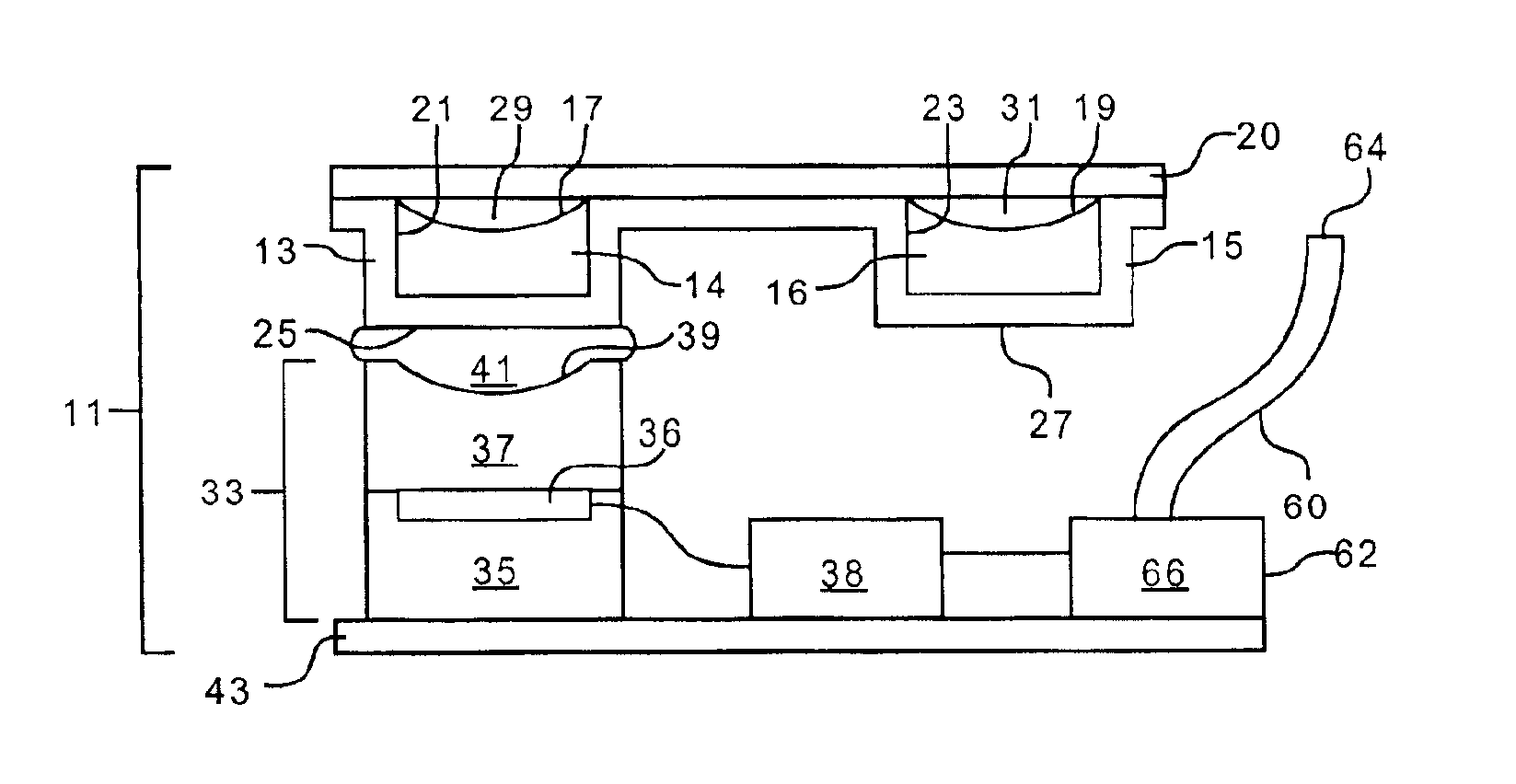
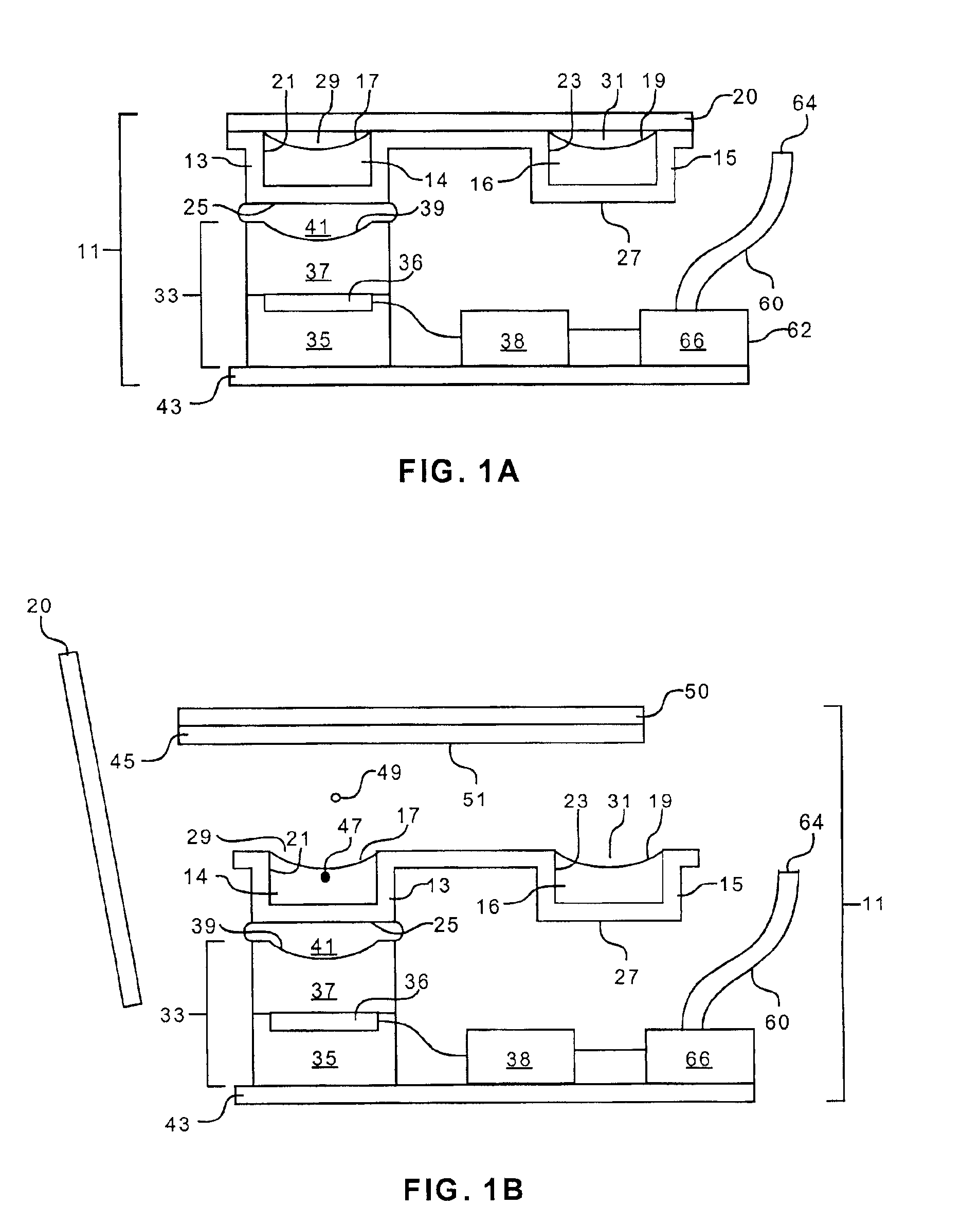
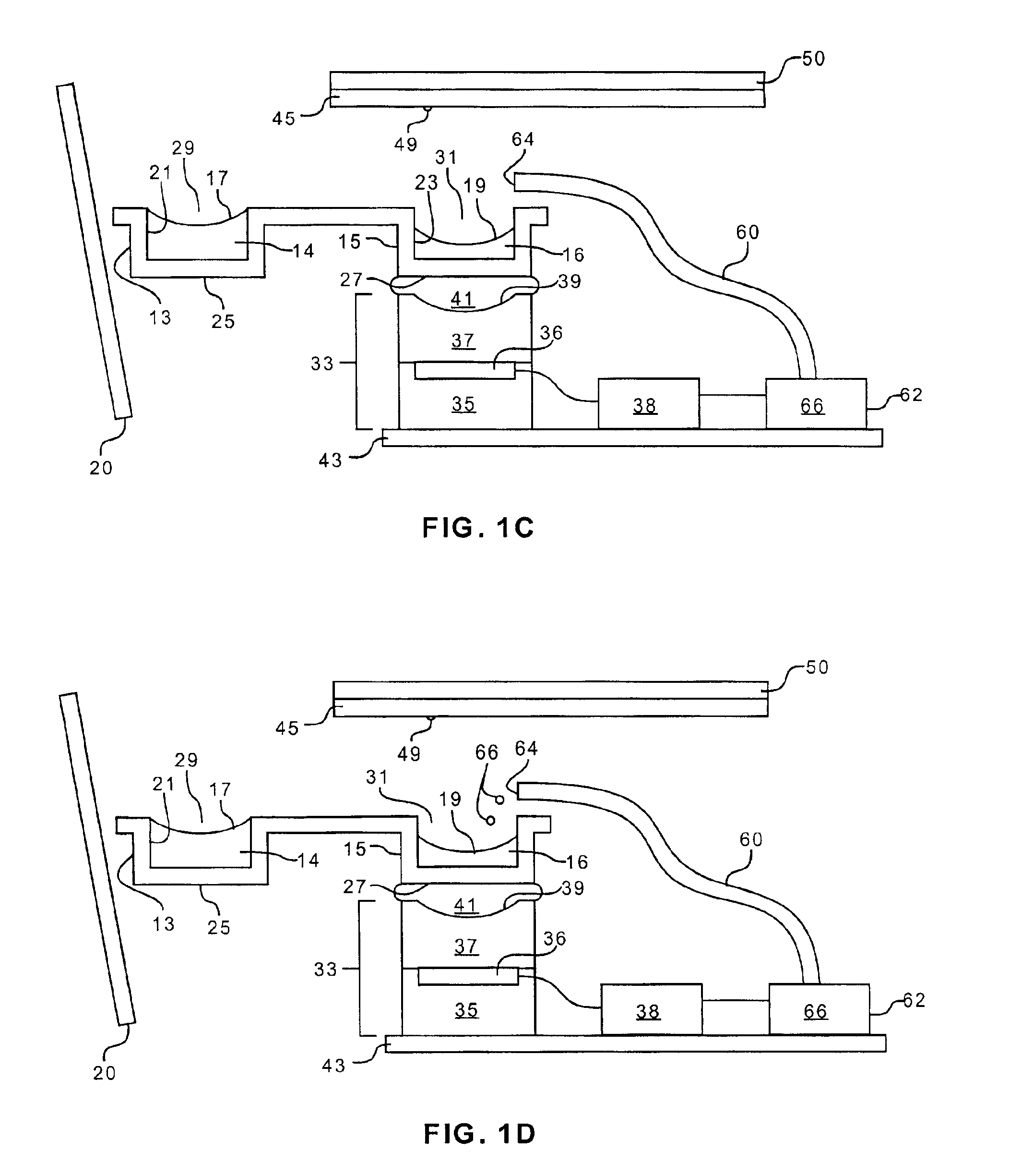
[0016]In addition or in the alternative, additional fluid may be introduced into the reservoir using an acoustic introducing means. In such a case, acoustic radiation may be applied to a source of additional fluid in a manner effective to transport additional fluid into the reservoir.
[0017]In a still further embodiment, the invention relates to a method for controlling the composition and/or volume of a fluid within a reservoir. The method involves monitoring for preferential removal of at least one constituent from a reser

Problems solved by technology

Such contact typically results in surface wetting that represents a source of unavoidable fluid waste, a notable drawback when the fluid to be transferred is rare and/or expensive.
For example, air bubbles can be entrapped or particulates may become lodged in tubing networks, which, in turn, could compromise fluid transport performance and result in diminished or misdirected fluid flow.
In some instances, complex robotic and/or automated systems may be configured to handle a large number of sample fluids.
In addition, when a fluid in a reservoir is exposed to an uncontrolled environment, environmental effects may play a role in detrimentally altering the reservoir composition and/or volume.
This, in turn, may cause dissolved compounds to precipitate out of solution, or suspended particles to agglomerate.
Thus, for example, when tubing is employed, such precipitation and/or agglomeration may clog the tubing network.
DMSO is highly hygroscopic and tends to absorb any ambient water with which it comes into contact.
In turn, the absorption of water dilu

Method used


Image

  • Acoustic control of the composition and/or volume of fluid in a reservoir
  • Acoustic control of the composition and/or volume of fluid in a reservoir
  • Acoustic control of the composition and/or volume of fluid in a reservoir

Examples


Embodiment Construction

[0022]Before describing the present invention in detail, it is to be understood that this invention is not limited to specific fluids, biomolecules, or device structures, as such may vary. It is also to be understood that the terminology used herein is for the purpose of describing particular embodiments only, and is not intended to be limiting.

[0023]It must be noted that, as used in this specification and the appended claims, the singular forms “a,”“an,” and “the” include plural referents unless the context clearly dictates otherwise. Thus, for example, reference to “a reservoir” includes a plurality of reservoirs, reference to “a fluid” includes a plurality of fluids, reference to “a characteristic” includes a combination of characteristics, and the like.

[0024]In describing and claiming the present invention, the following terminology will be used in accordance with the definitions set forth below.

[0025]The terms “acoustic coupling” and “acoustically coupled” as used herein refer ...


PUM


Abstract

The invention provides a device for controlling the composition and/or volume of a fluid within a reservoir. The device includes a reservoir adapted to contain at least one fluid, a means for monitoring a characteristic of the fluid contained in the reservoir, and a means for introducing additional fluid into the reservoir according to the fluid characteristic monitored by the monitoring means. The device also includes an acoustic generator for generating acoustic radiation. A dispensing means may be provided as well. Other devices and methods that use acoustic radiation to control the composition and/or volume of a fluid within a reservoir are included.

Description

TECHNICAL FIELD[0001]The invention relates generally to the use of acoustic energy to control the composition and / or volume of a fluid within a reservoir. In particular, the invention relates to devices and methods for acoustically monitoring and adjusting the composition and / or volume of a fluid in a reservoir. The invention is particularly suited for use with a reservoir containing at least one fluid comprised of a plurality of constituents, wherein at least one constituent may be preferentially removed from the reservoir.BACKGROUND[0002]There exists a need in pharmaceutical, biotechnological, and other scientific industries to be able to quickly screen, identify, and / or process large numbers or varieties of fluids. As a result, much attention has been focused on developing combinatorial techniques that require efficient, precise, and accurate fluid handling methods. In order to achieve sufficient efficiency and precision, certain disadvantages inherent in conventional fluid handl...

Claims


Application Information

Patent Timeline
IPC IPC(8): B01L3/02B65D90/48B65D90/00G01F23/296G01N35/10B01L3/00G01N35/00C40B40/06C40B40/10C40B60/14
CPCB01L3/0268B65D90/48G01F23/2962G01N35/1016B01J2219/00315B01J2219/00362B01J2219/00722B01J2219/00725B01L3/5085B01L2400/0436C40B40/06C40B40/10C40B60/14G01N2035/00237G01N2035/1025G01N2035/1034Y10S367/908Y10T137/0324Y10T137/7303Y10T137/7287
Inventor ELLSON, RICHARD N.MUTZ, MITCHELL W.
Owner LABCYTE
Why Eureka
Try Eureka