
Heat-dissipation device

Inactive Publication Date: 2005-08-23
IND TECH RES INST
View PDF18 Cites 14 Cited by
  • Summary
  • Abstract
  • Description
  • Claims
  • Application Information

AI Technical Summary

Benefits of technology

[0009]The primary objective of the invention is to specify a heat-dissipation device adopted for a helmet. The heat-dissipation device can improve heat-dissipation efficiency by working fluid circulated inside accompanying with the phase change at both evaporation and condensation.
[0012]The fourth objective of the invention is to specify a heat-dissipation device adopted for a helmet, in which the size of the vent of the heat-dissipation device can be controlled. The fifth objective of the invention is therefore to specify a heat-dissipation device adopted for a helmet, in which the heat-dissipation device is so comfortable that it is widely accepted in the marketplace and its producer's market share is increased thereby, in order to achieve business benefits.
[0013]According to the invention, the objectives are achieved by a heat-dissipation device adopted for a helmet. The helmet includes a shell that has an ergonomic inner configuration formed at the upper portion thereof. The heat-dissipation device includes a heat-transfer unit, at least one heat-dissipation unit connecting to the heat-transfer unit, at least one vent formed in a front of the heat-dissipation unit and furthermore a covering unit made of insulative materials. The heat-transfer unit has two-phase flow, the heat-dissipation unit extends outwardly so as to be exposed out of the shell, and the vent can be closed and opened alternatively. Whereby the heat-transfer unit provides a kind of two-phase flow that is capable of conducting heat rapidly, so as to remove heat gathered in the helmet and improve the wearer's comfort level.

Problems solved by technology

However, does perspiration really guarantee no blood?
But the wrapping layer has low diathermancy per se; heat will accumulate causing discomfort to the wearer.
The above patents for helmets fail to resolve the heat problems mentioned earlier.

Method used


Image

  • Heat-dissipation device
  • Heat-dissipation device
  • Heat-dissipation device

Examples


Embodiment Construction

[0024]According to the present invention, a heat-dissipation device adopted for a helmet includes a vent that can be closed alternatively and a heat sink that has been developed in the electronic field, such as a heat pipe or a heat exchanger, thus heat originally gathered inside the helmet can be delivered outwardly by the heat sink and dissipated outside via the vent, in order to increase the comfort of the helmet.

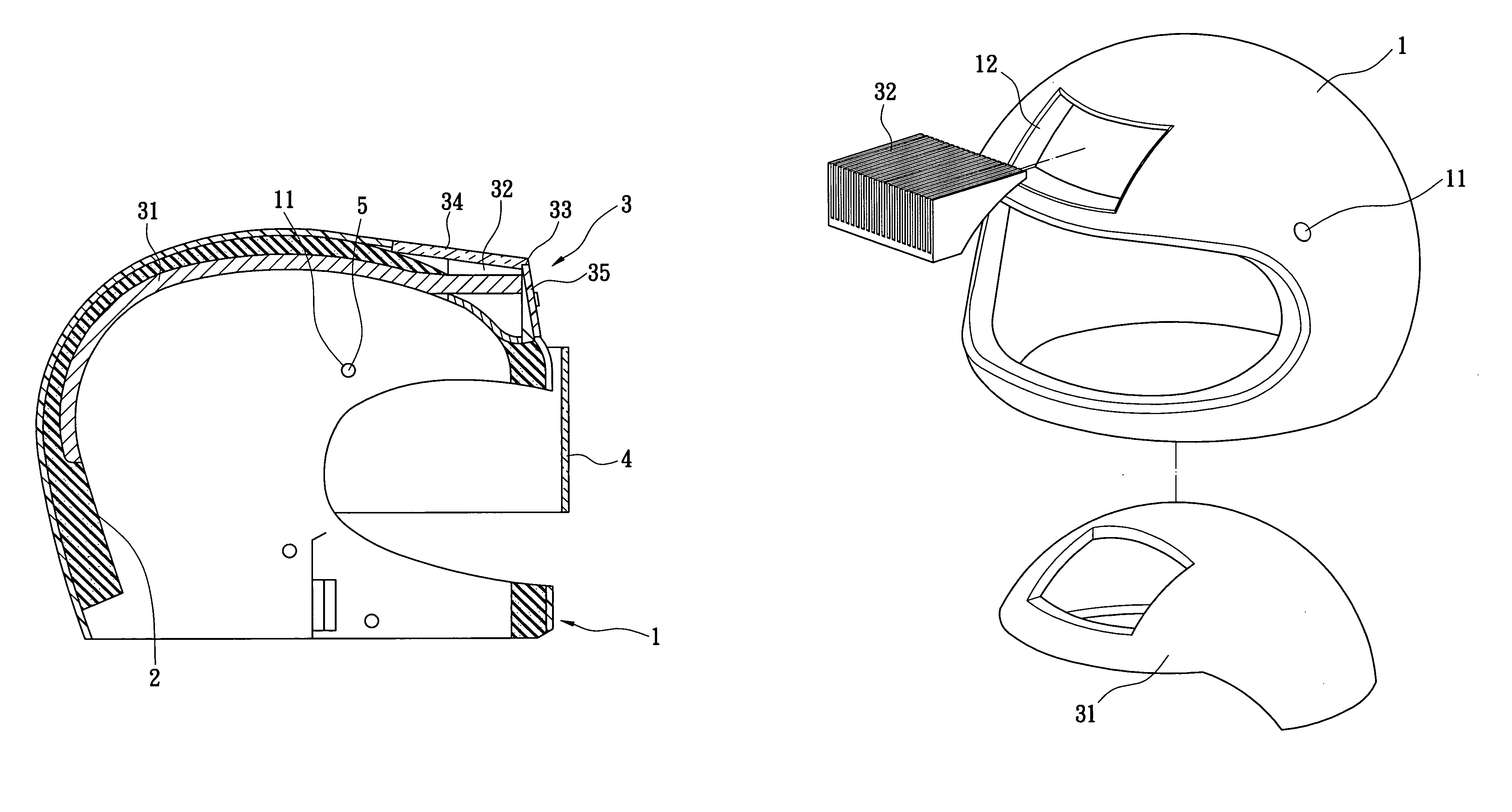
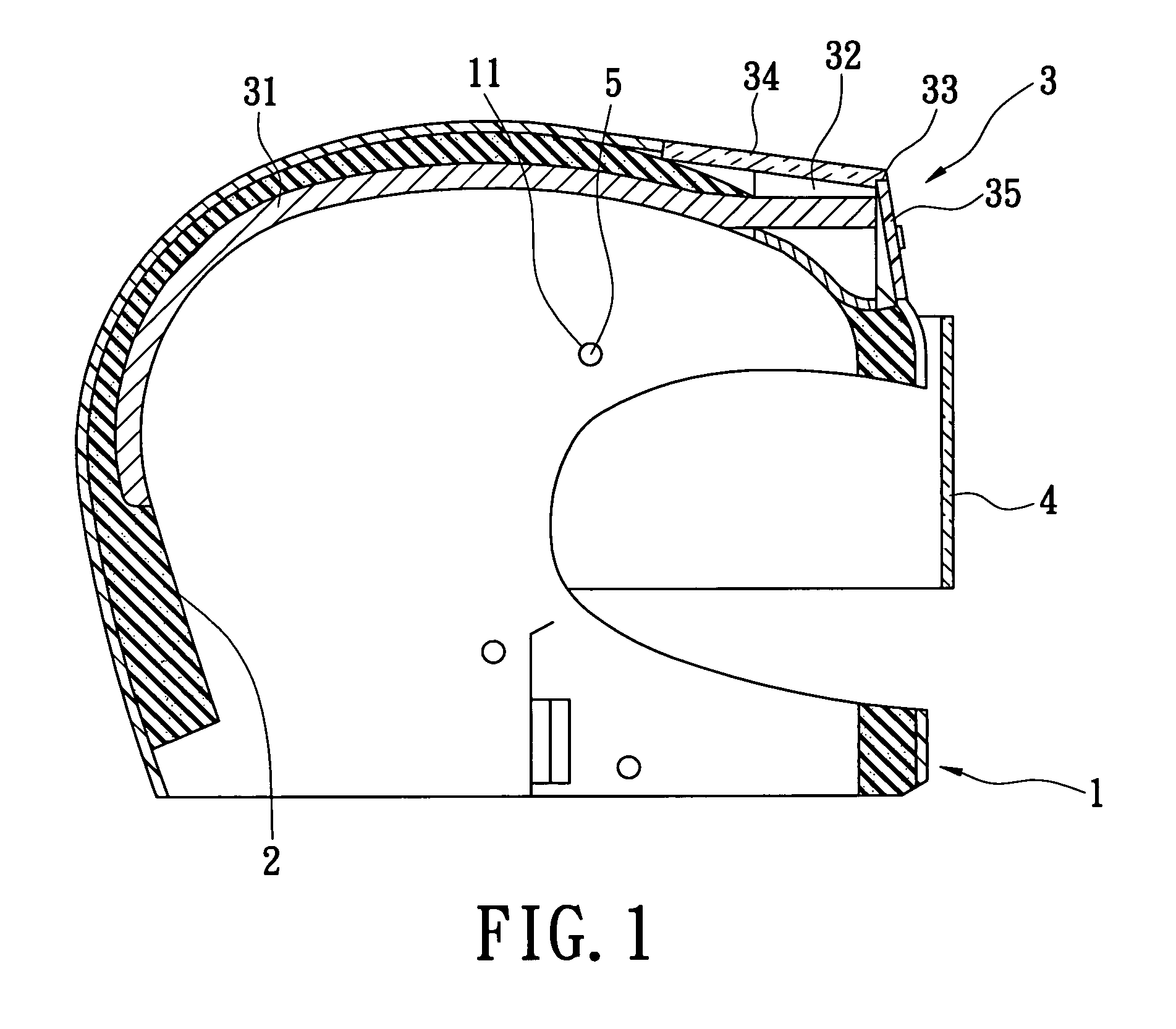
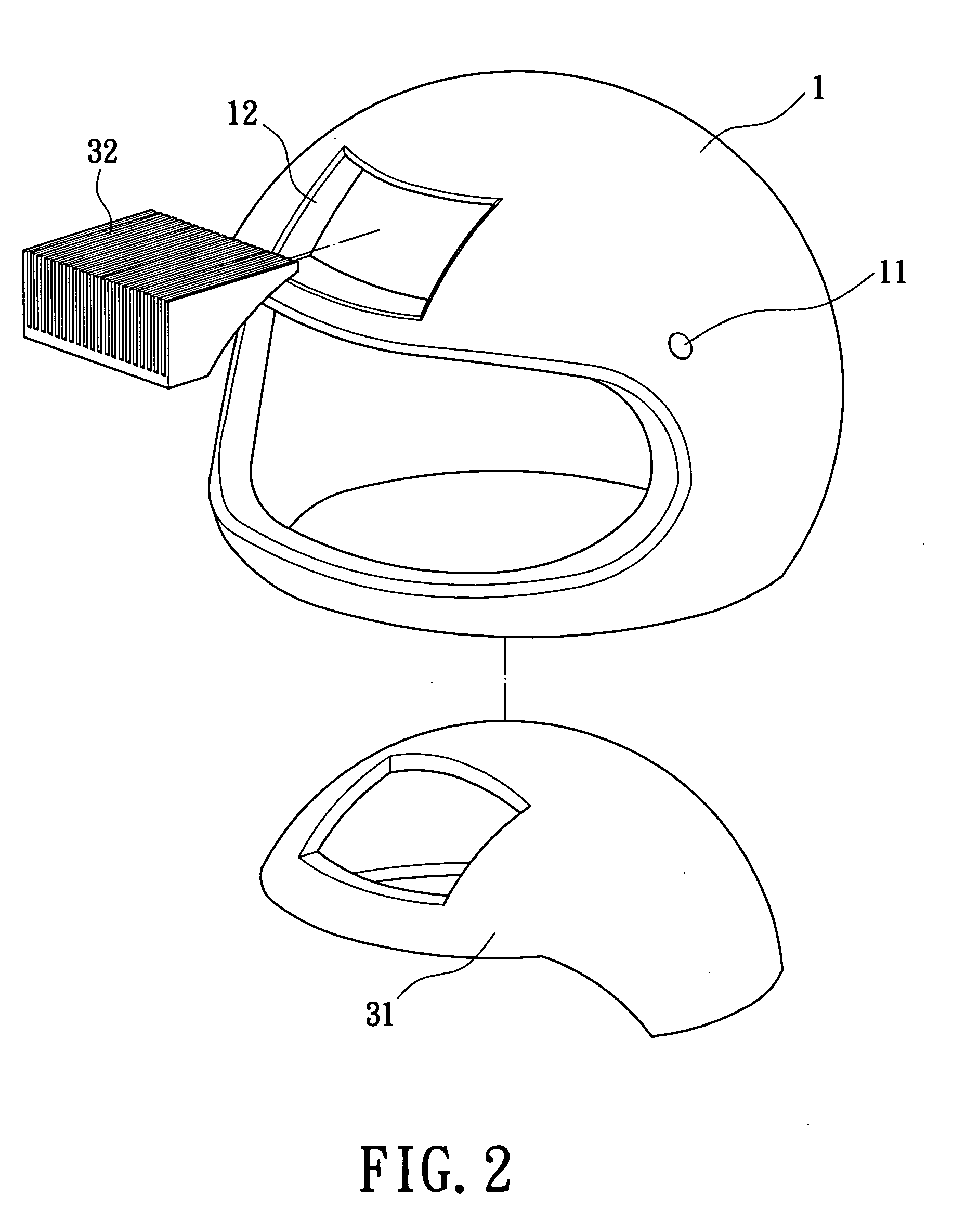
[0025]With respect to FIG. 1, a heat-dissipation device 3 adopted for a helmet according to the first embodiment is disclosed. The helmet includes a shell 1 that has an ergonomic inner configuration 2 formed at an upper portion thereof and covering a wearer's head. The heat-dissipation device 3 includes a heat-transfer unit 31, at least one heat-dissipation unit 32 connecting to the heat-transfer unit 31, at least one vent 33 formed in a front of the heat-dissipation unit 32, at least one covering unit 34 spreading over the heat-dissipation unit 32, and a shutter unit 35...


PUM


Abstract

A heat-dissipation device adopted for a safety helmet which includes a heat-transfer unit that functions as a heat pipe, a heat-dissipation unit connecting to the heat-transfer unit, a vent formed in a front of the heat-dissipation unit that can be closed and opened alternatively by a shutter unit in order to adjust the capacity of heat-dissipation thereof, and a covering unit made of insulative materials and spreading over the heat-dissipation unit. Whereby the heat-transfer unit provides a kind of two-phase flow that is capable of conducting heat rapidly, so as to remove heat gathered in the helmet and improve the comfort level for the wearer.

Description

BACKGROUND OF THE INVENTION[0001]1. Field of the Invention[0002]The present invention relates to a heat-dissipation device, and particularly relates to a heat-dissipation device applied inside a safety helmet.[0003]2. Background of the Invention[0004]Wearing safety helmets is the single most effective way to lower the risk of traumatic brain injury and death when someone rides a bike or a motorcycle. As new laws are introduced compelling people to wear helmets, a market for helmets has developed to a certain scope. The strongest reason for enforcing such laws is that sweating is better than bleeding. However, does perspiration really guarantee no blood? Does any helmet simultaneously give consideration to both comfort and safe?[0005]Two characteristics of a conventional helmet are safety and practicability. For safety, a wrapping layer is provided between the head and the outside of the helmet, in order to be prepared for the worst. The wrapping layer usually includes a synthetic re...

Claims


Application Information

Patent Timeline
IPC IPC(8): A42B3/04A42B3/28
CPCA42B3/285
Inventor YEH, LAN-KAITSAI, MING-JYELIN, CHE-WEICHEN, SHAO-WENSHYU, JIN-CHERNG
Owner IND TECH RES INST
Learn More