Quick change endform tool cartridge

a technology of endform and tool cartridge, which is applied in the direction of manufacturing tools, mechanical equipment, transportation and packaging, etc., can solve the problems that the endform cartridge system of the quick change tool cartridge has not been available befor

Inactive Publication Date: 2005-08-23
LOMAR MACHINE & TOOL
View PDF15 Cites 18 Cited by
  • Summary
  • Abstract
  • Description
  • Claims
  • Application Information

AI Technical Summary

Benefits of technology

[0015]Upon alignment of the tool holder groove or holes with the locking elements, the rotation of the actuator sleeve is permitted so as to cam the locking elements inwardly into the holder. Preferably, a spring force is imposed upon the actuator sleeve to bias the actuator toward the “locked” position to accident

Problems solved by technology

Quick change tool cartridge systems for endform

Method used


Image

  • Quick change endform tool cartridge
  • Quick change endform tool cartridge

Examples


Embodiment Construction

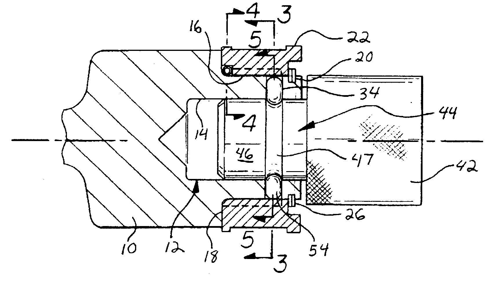
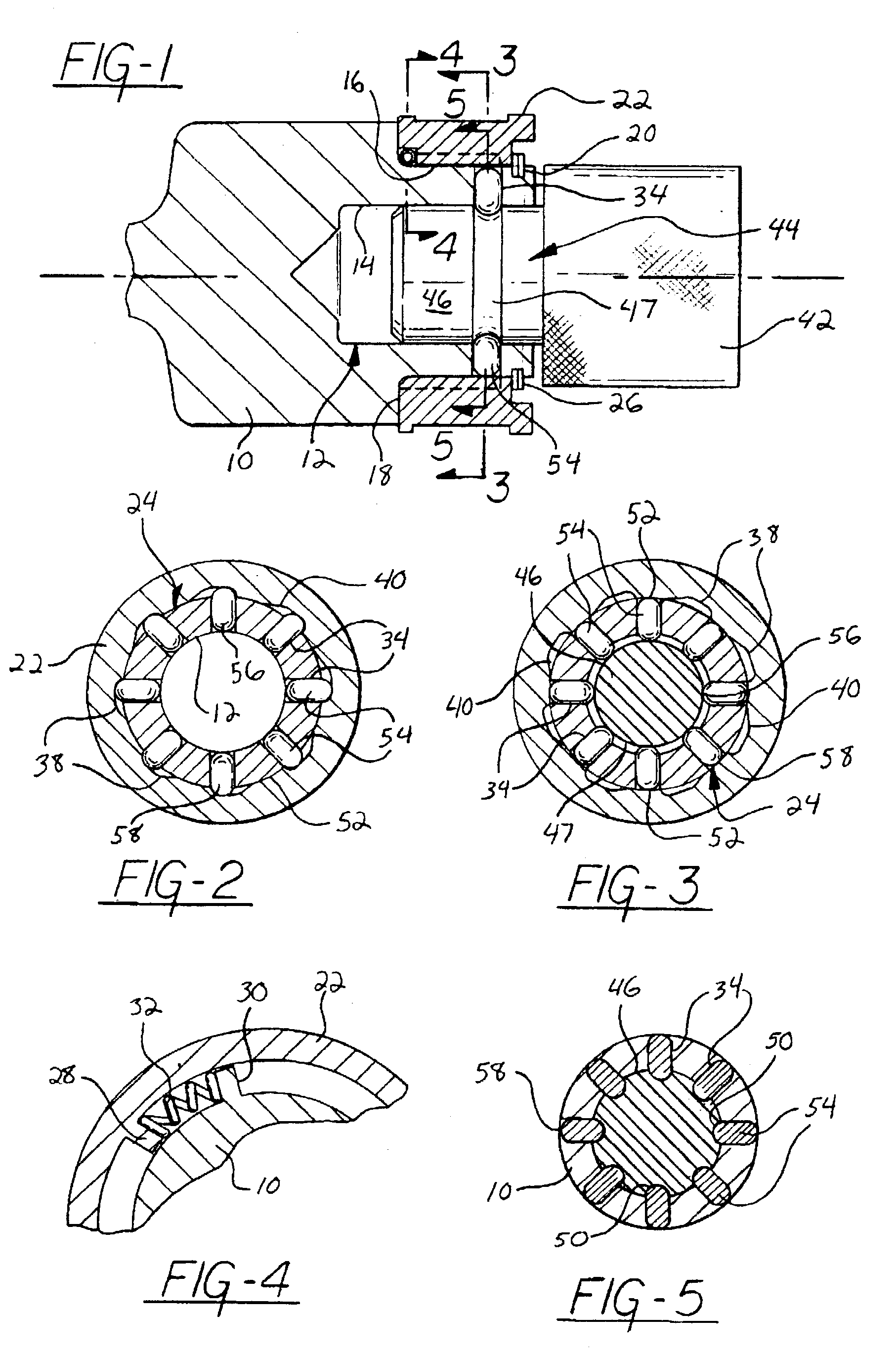
[0023]With reference to FIG. 1, the end tool support or stem is shown at 10. This support 10 would be the same as the tool stem 92 in U.S. Pat. No. 6,233,992. The support 10 includes an end in which the socket 12 is formed. The socket 12 constitutes a blind bore having cavity walls 14. Exteriorially, the support 10 is divided with a cylindrical surface 16 coaxial with the socket 12, and as will be appreciated from FIG. 1, the surface 16 is in axial alignment with the socket 12 and defines a radial shoulder 18. Further, an annular groove 20 is defined in the support 10 adjacent the end thereof and in the surface 16 as will be appreciated from FIG. 1.

[0024]The actuator sleeve 22 is rotatably mounted upon the support surface 16 and is provided with an exterior surface and shoulders as to be easily manually rotated. The actuator 22 includes a cylindrical inner surface engaging the support surface 16, and a snap ring 26 located within groove 20 axially prevents movement of the actuator s...


PUM


Abstract

A quick change tool cartridge for high production endform machines having a plurality of work stations mounted upon an indexable rotary head. The tool cartridge system is mounted upon the tool support by quick connect radially movable elements or pins radially displaced by a rotatable actuator sleeve. The locking elements cooperate with a groove, or holes, within the tool holder depending on whether or not relative rotation between the tool support and tool holder is desired.

Description

BACKGROUND OF THE INVENTION[0001]1. Field of the Invention[0002]The invention pertains to quick change tool cartridge systems for multiple station endforming machines wherein work stations are indexed about an axis of rotation.[0003]2. Description of the Related Art[0004]Endforming machines are used to axially upset the elongated workpieces, usually tubes, to form the end of the tube or produce an annular enlargement or diametric reduction in the tube. Endforming tools engage the end of the workpiece while the workpiece is firmly held against axially displacement.[0005]The endforming tools used with endforming machines of the above type are normally semi-permanently mounted upon the tool support by set screws and the like, whereby the tools may be accurately related to their holder, but it is necessary for the operator to stop the machine, rotate the tool holding screws or other elements, and then again start the machine once the new tool is in place. Quick change tool cartridge sys...

Claims


Application Information

Patent Timeline
IPC IPC(8): B23B31/10B23B31/107
CPCB23B31/1074B23B2260/02Y10T279/17717Y10T279/17803B23B2260/136B23B31/1072B23B31/10741
Inventor GEISMAN, RONALD E.WHITE, STEVEN A.
Owner LOMAR MACHINE & TOOL
Why Eureka
Try Eureka