Electrical connector assembly structure

a technology of electrical connectors and assembly structures, applied in the direction of coupling device connections, coupling protective earth/shielding arrangements, electric discharge lamps, etc., can solve the problems of undoubtably high exceeding cost and fault rate in production, and achieve accurate data transmission and accurate spending of connection terminal life

Inactive Publication Date: 2005-08-23
NORTHSTAR SYST CORP
View PDF5 Cites 22 Cited by
  • Summary
  • Abstract
  • Description
  • Claims
  • Application Information

AI Technical Summary

Benefits of technology

[0008]Another purpose of the present invention is to provide a mating connector with a pressing area and groove-mount shields, which are mounted on the inner wall of the slot of the female connector assembly thereby allowing contact engagement. Without applying to the resistance of connection terminals, as used in convention electrical connectors, the present invention ensures the connection between the female connector assembly and mating connector of the electrical connector, thereby expending the lifetime of connection terminals and completing data transmission accurately.

Problems solved by technology

However, it is known to the connector manufacturers that the material of connectors is extruded plastic, whereas volume change with temperature of the material and the controllable scope of the error in extrusion are concerned, the flaw rate in production and the exceeding cost is undoubtly high.
Moreover, when connection terminals are used as the connecting components for connectors, the force they bear is very likely to cause distortion in them.

Method used


Image

  • Electrical connector assembly structure
  • Electrical connector assembly structure
  • Electrical connector assembly structure

Examples


Embodiment Construction

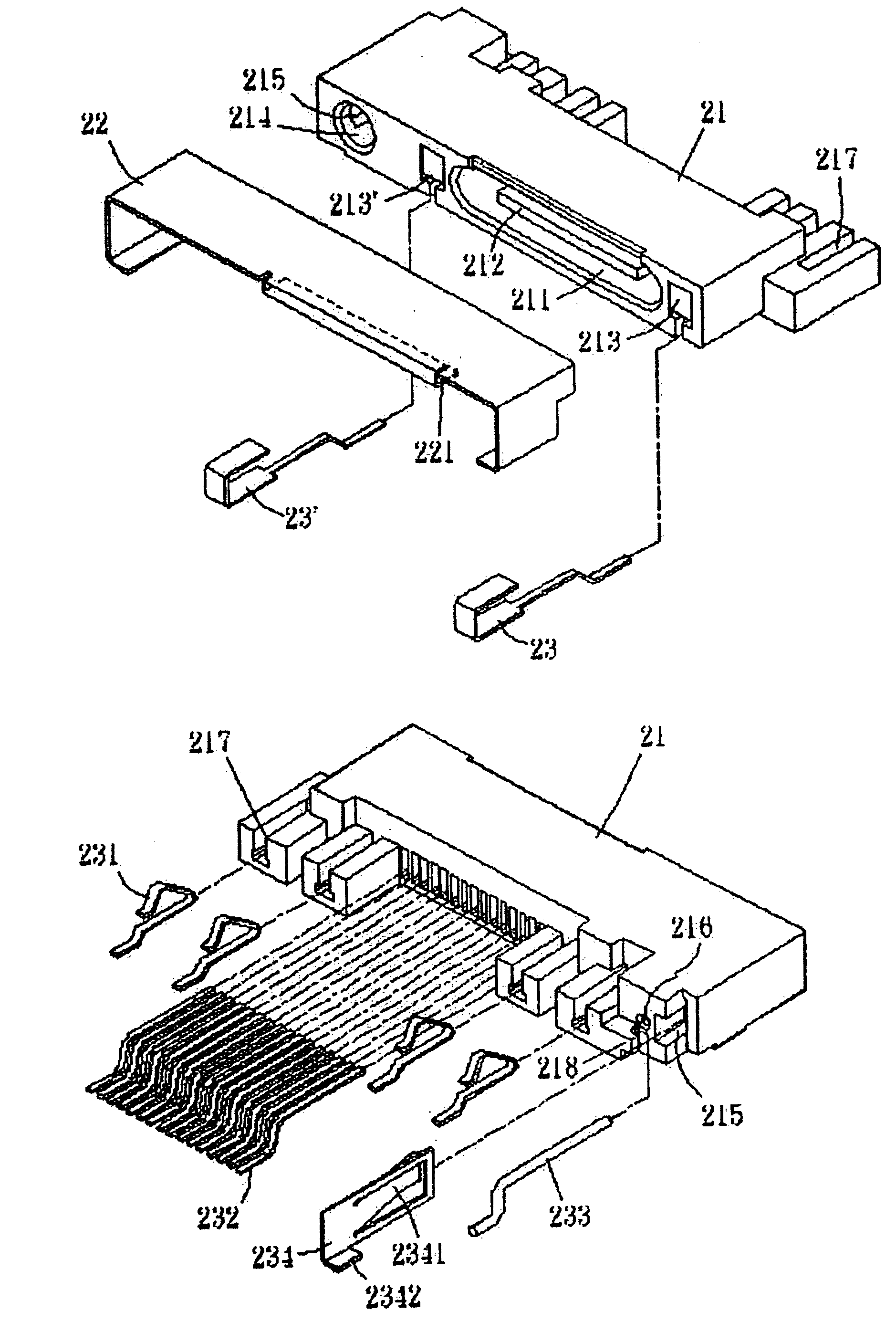
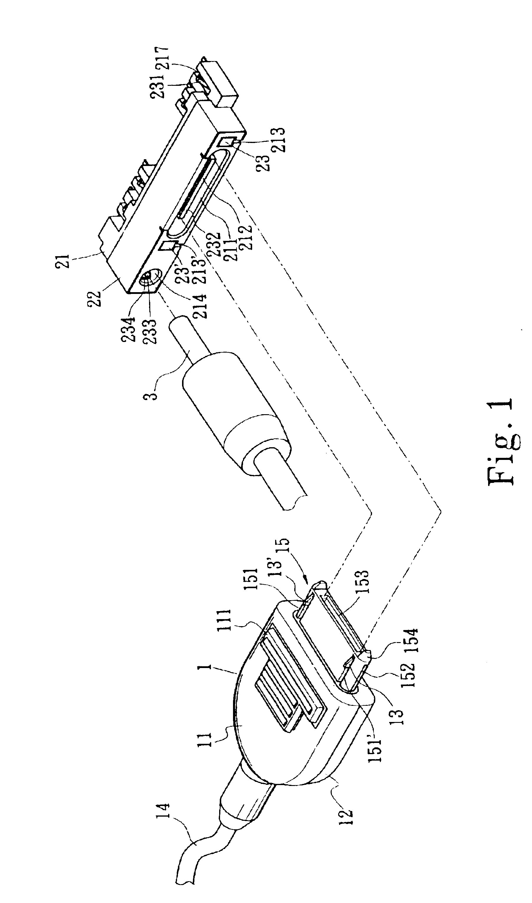
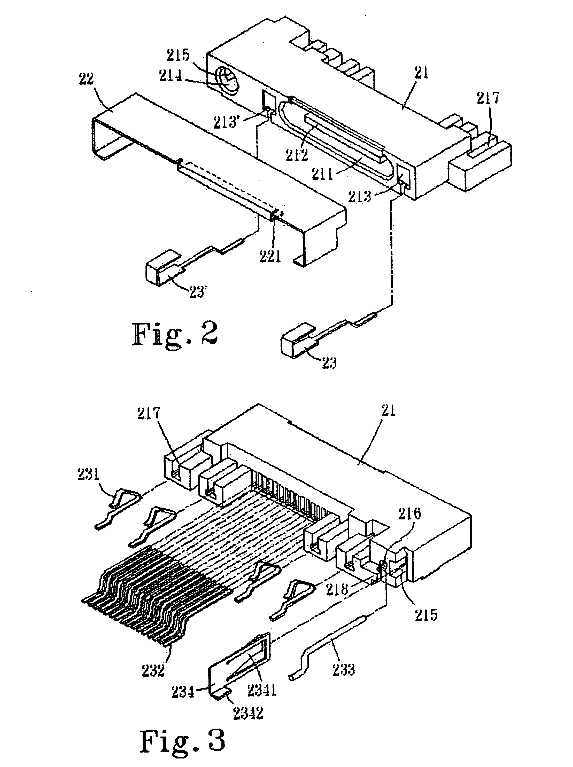
[0017]Referring to FIGS. 1, 2 and 3, the present invention comprises a mating connector (1) and a female connector assembly (2). The female connector assembly (2) herein is composed of a container base (21), a metal shield body (22), two correspondent U-shape pins (23, 23′), a plurality of connection terminals (231, 232), a power supply (233) and a stopping terminal (234). A slot (211) opened on one side of the container base (21) which is correspondent with a mating base (15) of the mating connector (1), as shown in FIG. 2. Moreover, a block (212) bulging from the center of the slot (211) comprises a plurality of connection terminals (232). Said block (212) is correspondent to a notch (153) on the mating base (15). When connecting, said block (212) mates with said notch (153) and connects with connection terminals (16) of the mating connector (1). An open slot (213, 213′) is disposed on each side of the slot (211) for receiving the U-shape pin (23, 23′). Said U-shape pins (23, 23′)...


PUM


Abstract

A modified structure for an electrical connector assembly provides connection between electronics, such as mobiles, notebooks, digital cameras, personal digital assistants (PDAs), wherein the electrical connector assembly includes a female connector assembly for insertion and connection, and a mating connector. By interlocking said female connector and mating connector and further in connection with the independent power supply, data and power supply are integrated in the structure design of the electrical connector. This prevents data loss, computer breakdown or interruption of power supply while transmitting data caused by loosening of connection between the mating connector and the female connector assembly.

Description

BACKGROUND OF THE INVENTION[0001]1) Field of the Invention[0002]The present invention relates to a modified structure for an electrical connector assembly, more particularly in connection between electronic products such as mobile phones, notebooks, digital cameras, personal digital assistants (PDAs) in order to integrate data transmission and power supply.[0003]2) Description of the Prior Art[0004]Electrical connectors are widely used in connection with electrical signals, such as the connection between signal source and various electronics or electrical equipments. Through them, signal source is able to provide signals or power to electronics or electrical equipments. Therefore, it is necessary to enhance the connection structure between female connector assembly and mating connector of electrical connectors in order to keep the line open.[0005]The technique in manufacturing the conventional electrical connector depends on the material and structure of connection terminals, and th...

Claims


Application Information

Patent Timeline
Patent Type & Authority Patents(United States)
IPC IPC(8): H01R13/658H01R24/00
CPCH01R13/6581H01R13/6582
Inventor SLOEY, JASON S.
Owner NORTHSTAR SYST CORP
Why Eureka
Try Eureka