Method and apparatus for the controlled formation of cavitation bubbles using target bubbles

a cavitation bubble and target bubble technology, applied in the direction of fluid jet surgical cutters, paper/cardboard articles, manufacturing tools, etc., can solve the problems of collateral damage, rapid damage and erosion of surfaces, and significant surface damage to even the hardest materials

Active Publication Date: 2005-08-23
LECLAIR MARK L
View PDF9 Cites 22 Cited by
  • Summary
  • Abstract
  • Description
  • Claims
  • Application Information

AI Technical Summary

Problems solved by technology

Pump impellers, boat props, and similar applications experience cavitation which can produce rapid damage and erosion of surfaces.
It has been well known for many years that ultrasonic cleaning devices, which function by the creation of cavitation bubbles, can produce significant surface damage to even the hardest of materials.
Without such control, concern of collateral damage cannot be avoided, especially when such tools are used in the human body in a medical application.
There are very few fabrication tools available that can cut, drill, peen, deform, or otherwise modify features of a surface on a submicron to nanometer scale.
This technology is not as flexible as may be required, and will have certain difficulties when applied to biological nanotechnology systems.
These situations may include eye surgery, for example, where placing an orifice structure inside the eye may not be practical.

Method used


Image

  • Method and apparatus for the controlled formation of cavitation bubbles using target bubbles
  • Method and apparatus for the controlled formation of cavitation bubbles using target bubbles
  • Method and apparatus for the controlled formation of cavitation bubbles using target bubbles

Examples


Embodiment Construction

)

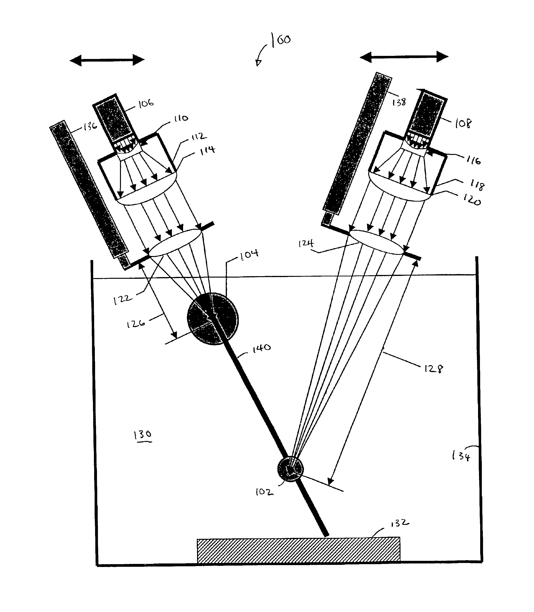
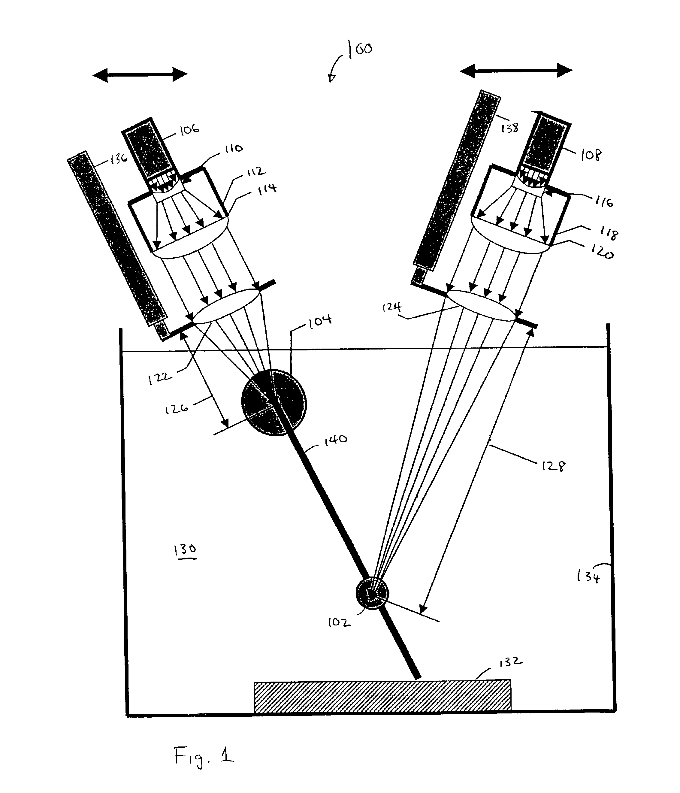
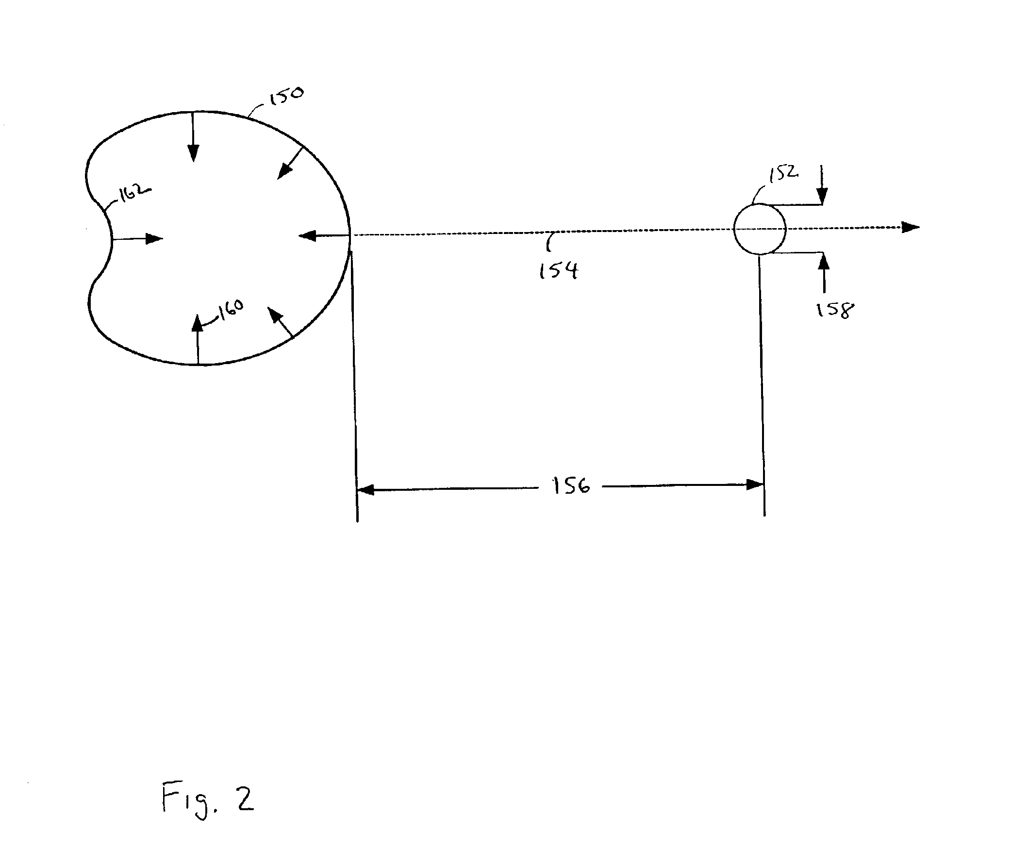
[0028]The control and direction of the re-entrant micro-jet formed during the collapse of a cavitation bubble can provide a powerful tool for performing various fabrication and manipulation functions at a submicron and nanometer scale. The above mentioned provisional U.S. patent application describes how these re-entrant micro-jets may be controlled through the use of an orifice placed between the work surface and the collapsing cavitation bubble. While the aforementioned techniques shall prove very useful for fabrication processes where the work surface can be placed in proximity to an orifice structure, there may be other applications where placing such a structure will be difficult or impossible. One example might be surgery inside the human eye, where a surgeon might wish to generate re-entrant micro-jets in the humus by focussing laser beams through the cornea. Another example might be to cut features into the side wall of micron sized pores in an integrated circuit structure ...


PUM

PropertyMeasurementUnit
velocitiesaaaaaaaaaa
pressureaaaaaaaaaa
pressureaaaaaaaaaa

Abstract

The present invention discloses a method and apparatus for the directed formation of a re-entrant micro-jet formed upon the collapse of a working cavitation bubble formed proximate to a work surface. A target bubble, formed between the work surface and the working cavitation bubble, is utilized to direct the re-entrant micro-jet to the work surface.

Description

CROSS REFERENCE TO RELATED APPLICATIONS[0001]This application is related to provisional application No. 60 / 350,849 filed Jan. 18, 2002 entitled METHOD AND APPARATUS FOR THE CONTROLLED FORMATION OF CAVITATION BUBBLES, claims benefit thereof, and is incorporated entirely herein by reference.BACKGROUND OF THE INVENTION[0002]1. Field of the Invention[0003]This invention relates generally to the formation and control of individual micron size and submicron size cavitation bubbles for use in nanofabrication operations. More particularly, embodiments of the invention teach methods and apparatus for control of a re-entrant micro-jet formed upon collapse of an individual or array of cavitation bubbles and directing the impact of the micro-jet toward a work surface or other objects with a high degree of precision.[0004]2. Description of the Related Art[0005]In general, the production of cavitation has been a phenomena many have tried to avoid. Cavitation in a liquid is the formation, growth, ...

Claims


Application Information

Patent Timeline
Patent Type & Authority Patents(United States)
IPC IPC(8): A61B18/20A61B18/26A61B17/32
CPCA61B18/26A61B17/3203A61B2017/32032A61B2018/263
Inventor LECLAIR, MARK L.
Owner LECLAIR MARK L
Why Eureka
Try Eureka