Wave energy converters utilizing pressure differences

a technology of wave energy converter and difference, applied in the field of energy conversion, can solve the problem of relatively small fall-off of operation efficiency, and achieve the effect of high operation efficiency

Inactive Publication Date: 2005-08-23
OCEAN POWER TECHNOLOGIES
View PDF15 Cites 49 Cited by
  • Summary
  • Abstract
  • Description
  • Claims
  • Application Information

AI Technical Summary

Benefits of technology

[0006]A feature of the present invention is that a relatively high efficiency of operation is obtained which is relatively insensitive to random variations of wave frequencies and amplitudes.

Problems solved by technology

While maximum efficiency of operation is attained when the anticipated waves are present, the fall-off of efficiency of operation is relatively small with variations of wave conditions.

Method used


Image

  • Wave energy converters utilizing pressure differences
  • Wave energy converters utilizing pressure differences
  • Wave energy converters utilizing pressure differences

Examples


first embodiment

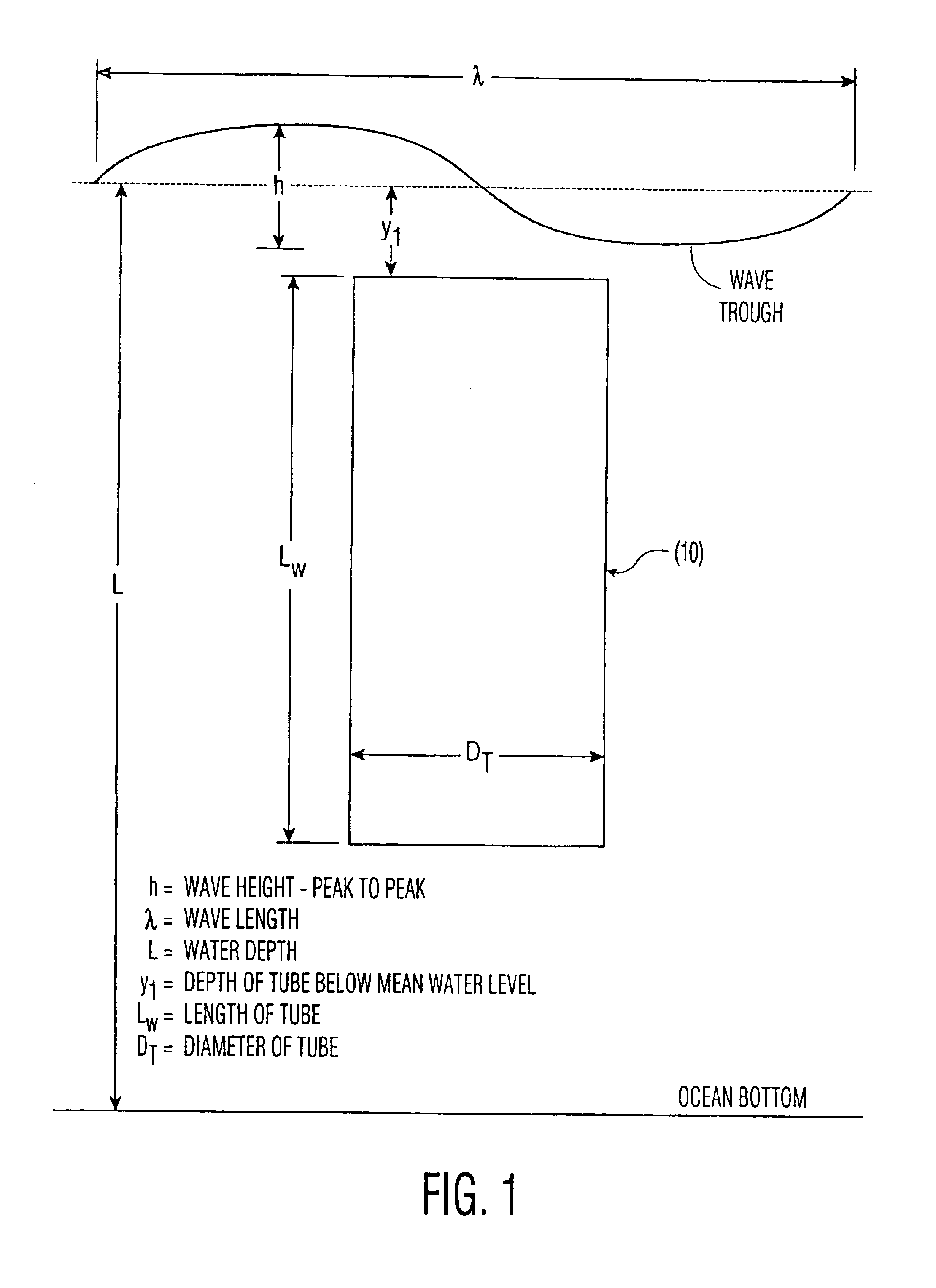
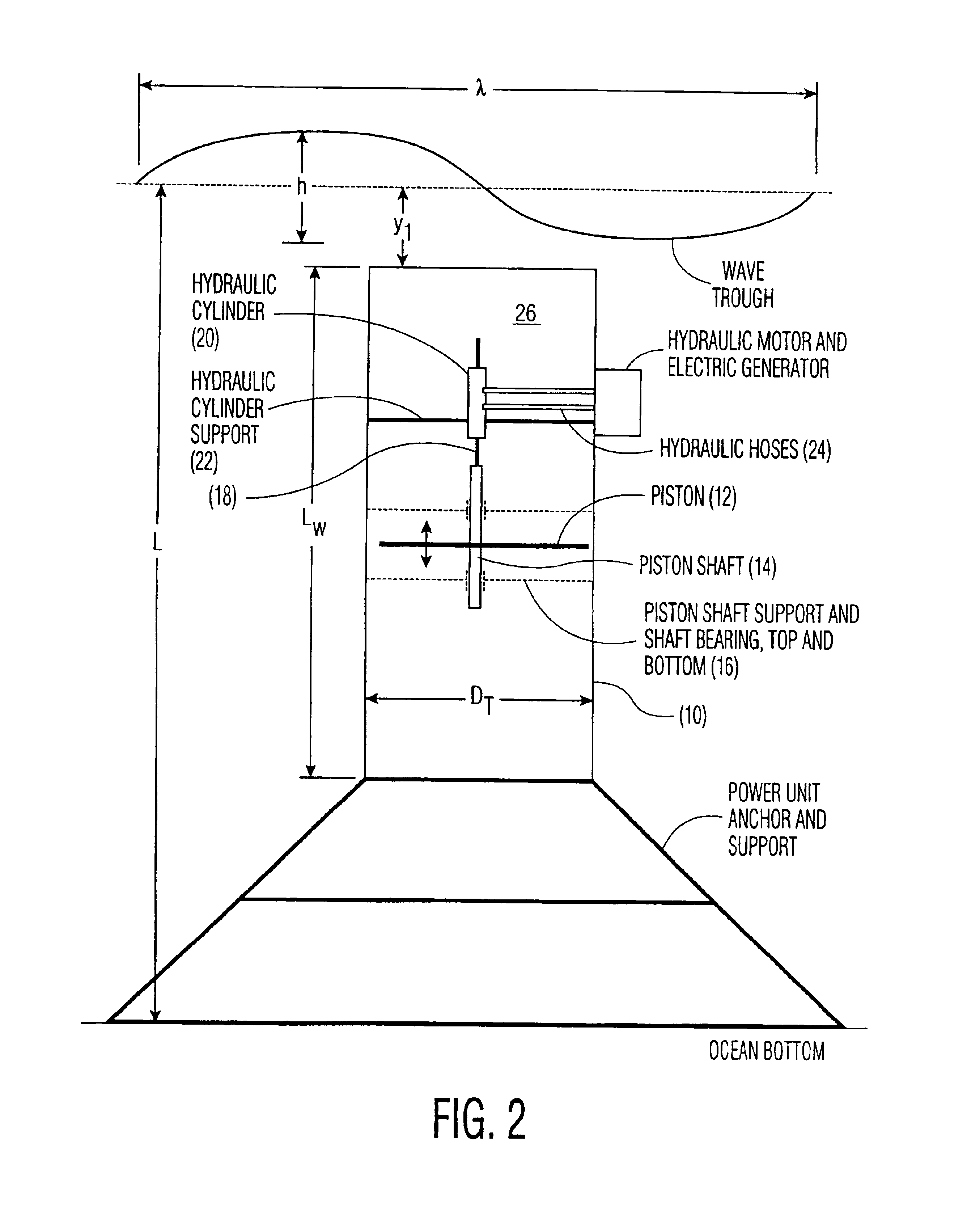
[0018]An apparatus according to the present invention is shown in FIG. 1. Shown schematically is an open-ended tube 10 disposed (as herewith described) in fixed, vertical orientation below the mean water level of a body of water, e.g., an ocean having wind driven surface waves. FIG. 1 also identifies parameters important in the practice of the invention, i.e., wave height, wave length, water depth, depth of the top of the tube below the water surface, length of the tube, and the diameter of the tube. The optimum depth for the lower end of the tube is dependent on the wavelength (λ) of the longest waves to be utilized in an efficient manner. The principle of operation is that the changes in water energy level, which can be expressed as changes in pressure, due to the passage of wave peaks and troughs, is highest near the surface, and these pressure changes decay exponentially with depth below the surface. Thus, the top of a long tube experiences relatively large pressure variations w...

second embodiment

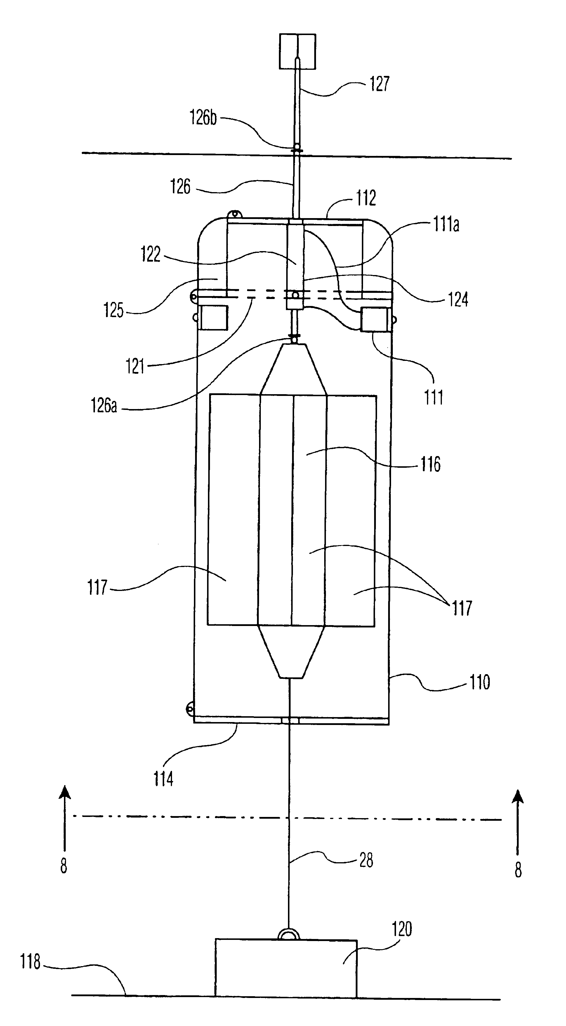
[0063]the invention, illustrated in FIGS. 7 through 9 is now described.

[0064]FIGS. 7-9 show a hollow tube 110 having a closed top end 112 and an open bottom end 114. As previously described in the first embodiment, the tube 110 is in vertical, submerged orientation but, unlike the tube 10 in the first embodiment, which is preferably fixed in place, the tube 110 of the second embodiment is vertically movable relative to a fixed support. Such support can be a rigid structure mounted on the water bed, but, especially in deep water, is preferably a float 116 fixedly moored to the water bed 118 by an anchor 120 and a chain or cable 128.

[0065]Most conveniently, the tube 110 encloses the float 116 and, because the tube is vertically elongated, the float 116 is similarly elongated.

[0066]The float 116 has a large buoyancy, and corresponds to a fixed structure rigidly mounted on the water bed but with the exception that some horizontal displacement of the float can occur in response to horizo...


PUM


Abstract

An elongated cylinder is fully submerged, in vertical orientation, just below the mean water level of, e.g., and ocean, and of a length, dependent upon surface waves of preselected wavelength, such that the top of the cylinder experiences relatively large pressure variations in response to over passing waves while the bottom of the cylinder experiences an almost steady pressure substantially independent of the over passing waves. The pressure differential over the length of the cylinder is used for causing relative movements between the cylinder and adjoining water, and such relative movements are used for driving a piston of an energy converter. The cylinder can be hollow and in fixed location for causing water movements through the cylinder, or the cylinder can move through the water relative to a fixed transducer. In one version of the movable cylinder, the transducer is fixedly mounted on a fixed in place float disposed within the movable cylinder. In a second version, the transducer is fixedly mounted beneath the movable cylinder on the ocean floor, and the cylinder is coupled to the transducer.

Description

[0001]This is a division of U.S. patent application Ser. No. 09 / 763,247, filed Oct. 15, 2001, now U.S. Pat. No. 6,768,216 which application claims the benefit of the filing date of international application PCT / US00 / 14652, filed 26 May 2000 which claims the benefit of Povisional application No. 60 / 136,189, filed May 27, 1999.BACKGROUND OF THE INVENTION[0002]This invention relates to the conversion of energy from naturally occurring sources of mechanical energy, and particularly to the conversion of the mechanical energy present in ocean surface waves to useful energy, particularly electrical energy.[0003]In many known systems for capturing surface wave energy, a float is used for being vertically oscillated in response to passing waves. The float is rigidly coupled to an energy converter which is driven in response to vertical movements of the float. In one system, described in U.S. Pat. Nos. 4,773,221 and 4,277,690 (the subject matter of which is incorporated herein by reference), ...

Claims


Application Information

Patent Timeline
Patent Type & Authority Patents(United States)
IPC IPC(8): F03B13/14F03B13/00
CPCF03B13/148Y02E10/38Y02E10/30
Inventor CARROLL, CHARLES B.BELL, MEREDITH
Owner OCEAN POWER TECHNOLOGIES
Why Eureka
Try Eureka