Rotating electric machine and cooling structure for rotating electric machine

a cooling structure and electric machine technology, applied in the direction of dynamo-electric machines, electrical apparatus, magnetic circuit shapes/forms/construction, etc., can solve the problems of reducing the output of the rotating electric machine and the difficulty of this type of cooling structure to realize sufficient reductions in and achieves a large reduction. the effect of sufficient reduction of the temperature of the stator cor

Inactive Publication Date: 2005-08-23
NISSAN MOTOR CO LTD
View PDF12 Cites 31 Cited by
  • Summary
  • Abstract
  • Description
  • Claims
  • Application Information

AI Technical Summary

Benefits of technology

[0006]It is therefore an object of this invention to provide a cooling structure which does not cause a large reduction in the output of a rotating electric machine and which at the same time realizes sufficient reductions in the temperature of a stator core. It is a further object of this invention to provide a rotating electric machine adapted for use with this cooling structure.

Problems solved by technology

However when a passage for the cooling medium is formed in the stator core, it is sometimes the case that the passage for the cooling medium hinders the flow of magnetic flux and reduces the output of the rotating electric machine.
However in this type of cooling structure, since the coils are wound on the teeth of the stator core, the area of contact of the cooling medium with the stator core is small and the cooling passage is not provided in direct contact with the stator core.
Therefore it is difficult for this type of cooling structure to realize sufficient reductions in the temperature of the stator core.

Method used


Image

  • Rotating electric machine and cooling structure for rotating electric machine
  • Rotating electric machine and cooling structure for rotating electric machine
  • Rotating electric machine and cooling structure for rotating electric machine

Examples


example 1-i

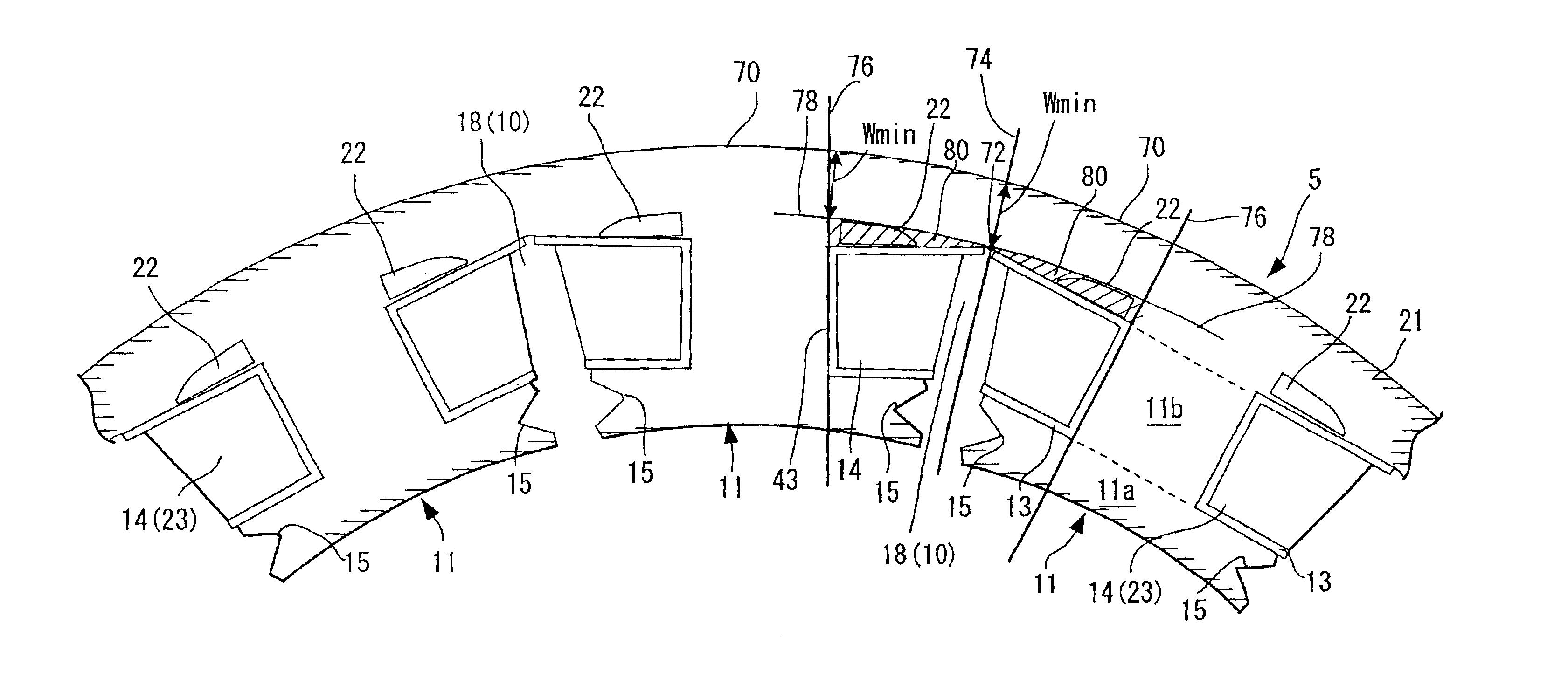
[0058]FIG. 4A is a partially enlarged end view of a stator core 5 including the teeth 11. A single large cooling medium passage 22 is provided in the region 80 in FIG. 3 through the back core 21. Referring to FIG. 4A, the opening of the cooling medium passage 22 is disposed on the outer peripheral side with respect to the stator coil 14. The opening is further disposed on both sides of the insulating body 12 which covers the end face of the teeth 11. As a result, cooling oil in the cooling jacket 6A is introduced into the other cooling jacket 6B through the cooling medium passage 22 and cools the base of the teeth 11.

[0059]The arrow on the dot-dash line in FIG. 4B shows the direction of flow of the magnetic field. In EXAMPLE 1-I, even when the cooling medium passage 22 is provided on the back core 21, the magnetic flux of the stator core 5 flows smoothly without sharply bending in the back core 21. This is due to the fact that although the width of the flux passage is narrowed as a ...

example 1-ii

[0062]FIG. 7 is a partially enlarged end view of a stator core 5 provided with a cooling medium passage 22 according to EXAMPLE 1-II.

[0063]Referring to FIG. 7, a plurality of cooling medium passages 22′ are disposed in region 80 of the stator core 5 as shown in FIG. 3. The cooling medium passage 22 as described with reference to EXAMPLE 1-II is divided into a plurality of cooling medium passages 22′. In comparison to a single large cooling medium passage 22, the formation of a plurality of cooling medium passages 22′ increases the mechanical strength of the back core 21. Consequently deformation of the back core 21 can be avoided. Although the total cross-sectional area of the passage of the cooling medium does not increase, the contact area of the cooling oil and stator core 5 is increased, thereby improving cooling performance of the teeth 11 in comparison to EXAMPLE 1-I. Consequently it is possible to further improve cooling performance of the stator core 5 of the rotating electr...

example 1-iii

[0064]FIG. 8 is a partially enlarged end view of a stator core 5 provided with a cooling medium passage 22 according to EXAMPLE 1-III. In FIG. 8, the coil end of the stator coil 14 and the insulating body 12 are omitted.

[0065]In FIG. 8, a plurality of cooling medium passages 22′ are disposed in region 80 shown in FIG. 3. The cooling medium passages 22′ comprise a plurality of grooves opening onto the wall face of the housing 23 of the stator coil 14 of the slot 10. The rear face of the insulating paper 13 is retained on the wall 61 between the plurality of grooves during winding operations of the stator coils 14. Thus winding operations for the stator coils 14 can be performed in the same manner as when a cooling medium passage 22′ does not open onto the housing 23. Furthermore in comparison to EXAMPLE 1-I, it is possible to increase the contact area of the cooling oil and stator core 5 and to further improve cooling performance with respect to the teeth 11.

[0066]Since the cooling m...


PUM


Abstract

A cooling structure and a rotating electric machine with the cooling structure are provided. The cooling structure produces sufficient reductions in the temperature of the stator core while at the same time not causing a large reduction in the output of the rotating electric machine. The rotating electric machine is provided with a first cooling medium passage formed in the slot. In addition, a second cooling medium passage is provided which extends in parallel to the first cooling medium passage and allows flow of the same cooling medium as the first cooling medium passage. The stator core comprises at least a section of the passage wall of the second cooling medium passage. The second cooling medium passage is disposed so that the second cooling medium passage does not impede the flow of magnetic flux in the stator core.

Description

FIELD OF THE INVENTION[0001]This invention relates to a rotating electric machine and a cooling device for a rotating electric machine.BACKGROUND OF THE INVENTION[0002]In a rotating electric machine functioning as a motor, or a generator or a motor / generator, it is preferred that the stator core and the rotor are cooled in order prevent generation of heat.[0003]Tokkai Hei 5-236705 published by the Japanese Patent Office in 1992, Tokkai Hei 7-322565 published by the Japanese Patent Office in 1995 and Tokkai Hei 11-69721 published by the Japanese Patent Office in 1999 disclose a rotating electric machine provided with a passage for a cooling medium in a stator core.[0004]The cooling of the stator core allows the indirect cooling of the rotor. Therefore when the stator core is sufficiently cooled, it is not necessary to provide a cooling structure for the rotor. However when a passage for the cooling medium is formed in the stator core, it is sometimes the case that the passage for the...

Claims


Application Information

Patent Timeline
Patent Type & Authority Patents(United States)
IPC IPC(8): H02K1/12H02K3/24H02K1/20H02K3/04
CPCH02K1/20H02K3/24
Inventor KANEKO, YUTAROKITADA, SHINICHIROKIKUCHI, TOSHIOTSUNEYOSHI, TAKASHI
Owner NISSAN MOTOR CO LTD
Why Eureka
Try Eureka