Light-quantity control apparatus and optical apparatus

a control apparatus and light-quantity technology, applied in the direction of shutters, camera filters, instruments, etc., can solve the problems of difficult to make the light-quantity control apparatus and the lens adjacent thereto sufficiently close, and the shutter close operation may not be smooth, so as to achieve sufficient reduction of the thickness of the optical apparatus and smooth shutter operation

Active Publication Date: 2014-05-01
CANON DENSHI KK
View PDF0 Cites 7 Cited by
  • Summary
  • Abstract
  • Description
  • Claims
  • Application Information

AI Technical Summary

Benefits of technology

[0012]The present invention provides a light-quantity control apparatus having a light-quantity control blade formed in a curved or bent shape and thereby enabling sufficient reduction of a thickness of an optical apparatus including the light-quantity control apparatus in its optical axis direction and allowing a smooth shutter operation. The present invention also provides an optical apparatus including the above light-quantity control apparatus.

Problems solved by technology

In addition, when the cam boss portion provided in the stop blade penetrates the cam groove portion of the driving ring to protrude on an opposite side to the driving ring, the protruding cam boss portion may hinder the lens from being inserted into the concave space.
That is, it is difficult to make the light-quantity control apparatus and the lens adjacent thereto sufficiently close to each other and to miniaturize the lens barrel in the retracted state.
As a result, the shutter close operation may not be smoothly performed.

Method used


Image

  • Light-quantity control apparatus and optical apparatus
  • Light-quantity control apparatus and optical apparatus
  • Light-quantity control apparatus and optical apparatus

Examples


embodiment 1

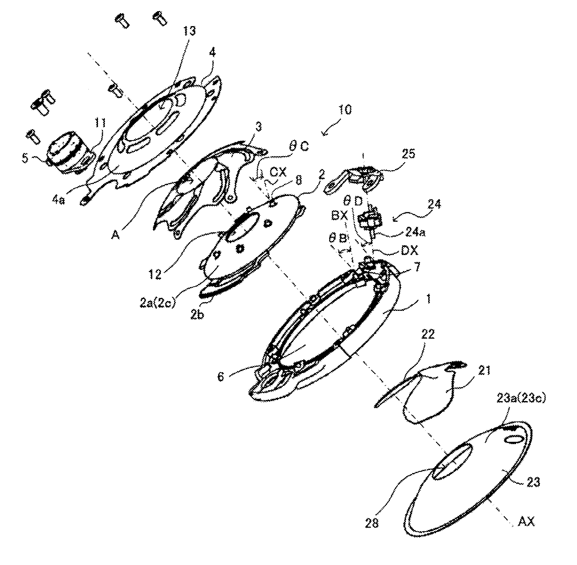
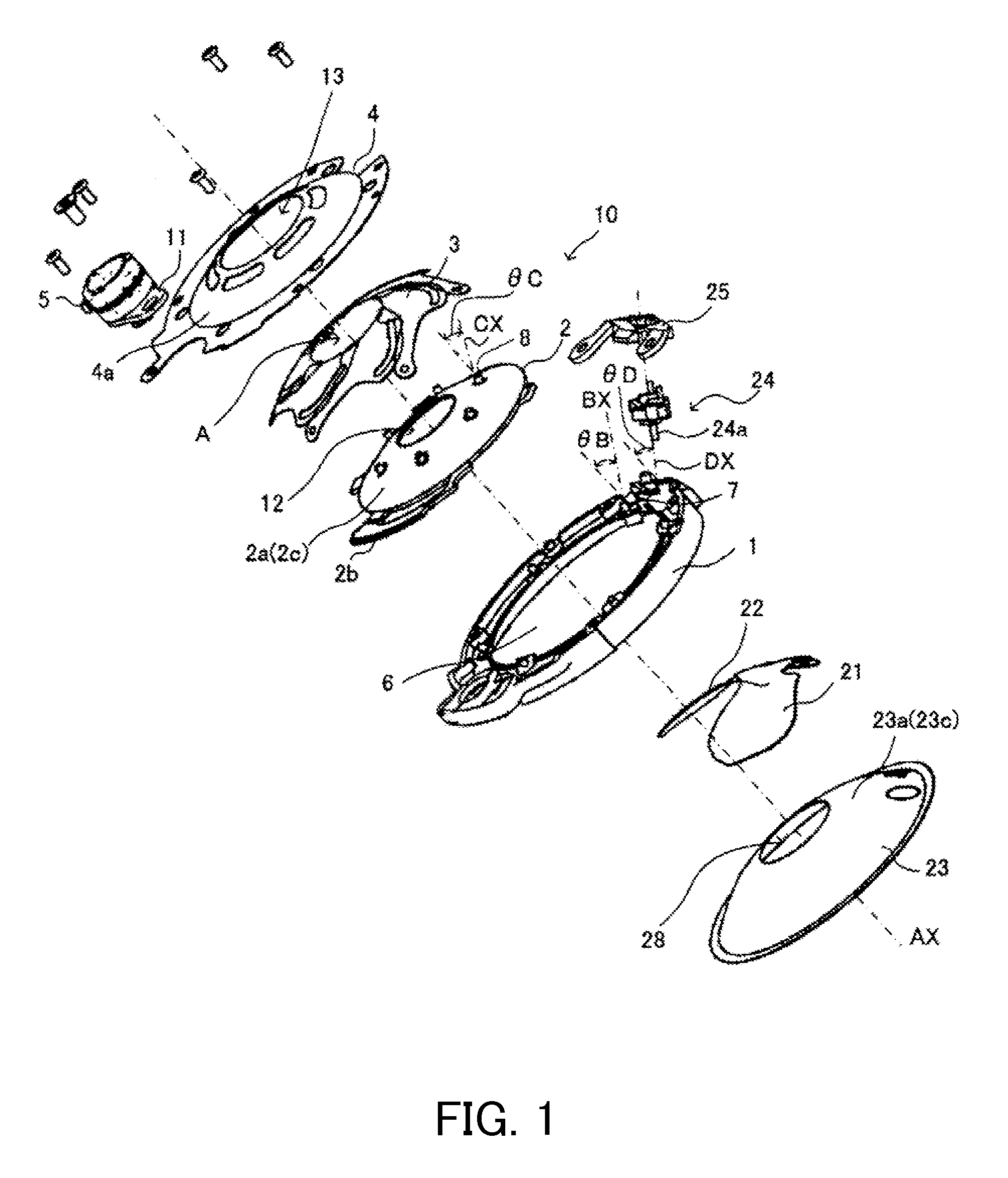
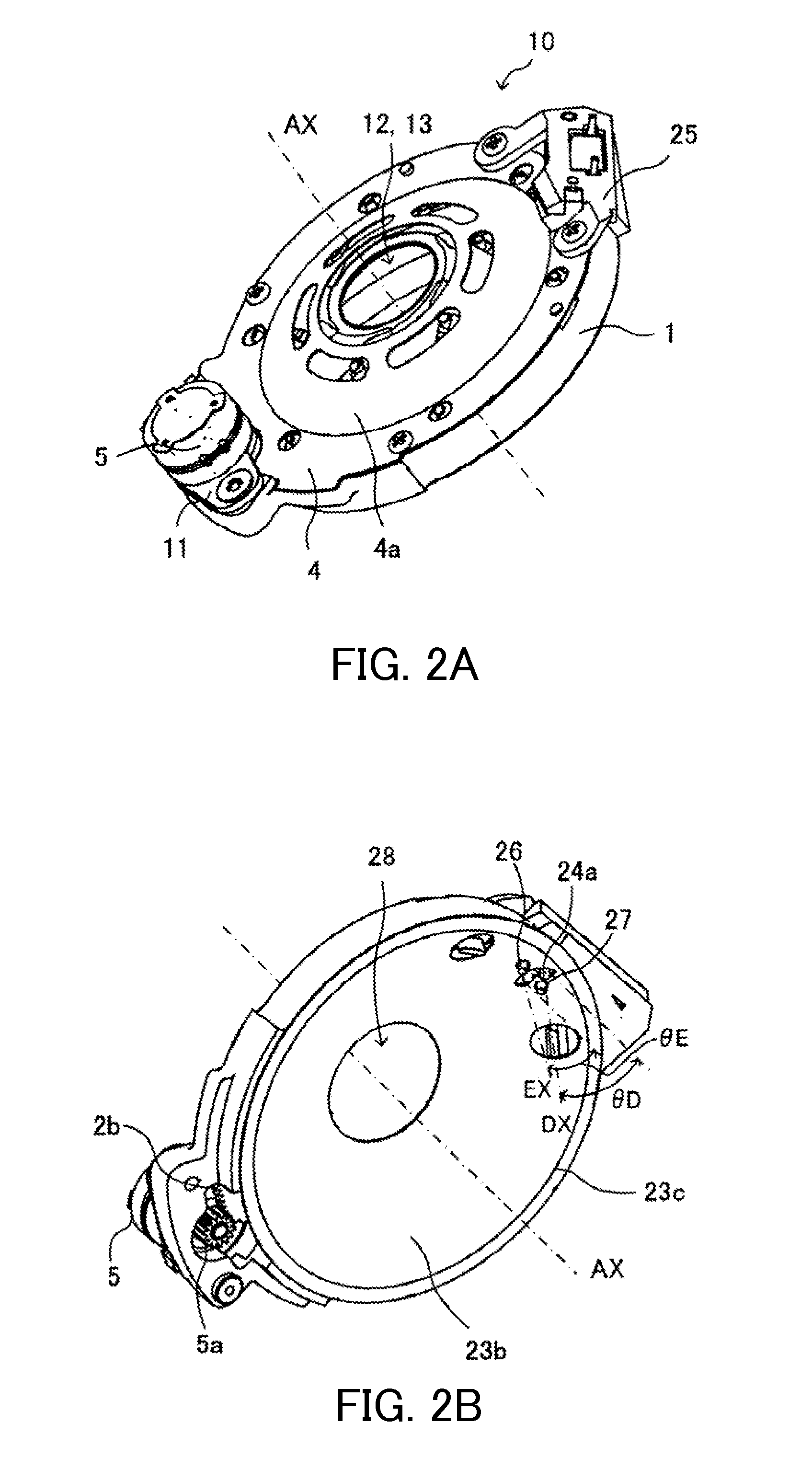
[0036]FIGS. 1, 2A and 2B illustrate an iris type aperture stop / shutter apparatus 10 as a light-quantity control apparatus that is Embodiment 1 of the present invention. In these drawings, a base plate 1 as a base member formed in a ring shape has an opening 6 formed in an inner circumferential part thereof. In the following description, an axis passing through a center of the aperture stop / shutter apparatus 10 and orthogonal to an opening plane of the opening 6 formed in the base plate 1 and an aperture plane of each fixed aperture described below is referred to as “an optical axis AX,” and a direction where the optical axis AX extends is referred to as “an optical axis direction.” In addition, a direction orthogonal to the optical axis direction is referred to as “a radial direction.” A stop blade-supporting boss portion (protruding portion) 7 as a stop blade-supporting portion is formed at each of a plurality of circumferential places of a ring portion surrounding the opening 6 of...

embodiment 2

[0085]FIG. 17 illustrates a camera (a video camera or a still camera) as an optical apparatus in which the aperture stop / shutter apparatus 10 described in Embodiment 1 is installed. The camera includes a camera body 50, a plurality of lenses 51 and 53 constituting an image capturing optical system, and an image sensor 52 such as a charge-coupled device (CCD) sensor or a complementary metal oxide semiconductor (CMOS) sensor to photo-electrically convert an object image formed by the image capturing optical system.

[0086]A controller 54 such as a central processing unit (CPU) controls operations of the drivers 5 and 24 of the aperture stop / shutter apparatus 10 and the image sensor 52.

[0087]In such a camera, as described in Embodiment 1 with reference to FIG. 3, at least part (convex surface) of the lens 51 adjacently disposed to the aperture stop / shutter apparatus 10 in the optical axis direction and a lens holding member 55 for holding the lens 51 can be inserted into the concave spac...

embodiment 3

[0094]FIGS. 9 and 10 illustrate an iris type aperture stop apparatus 110 as a light-quantity control apparatus that is Embodiment 3 of the present invention. In FIGS. 9 and 10, reference numeral 101 denotes a base plate as a base member in which a first fixed aperture 106 as a fixed light-passing aperture is formed in its radially central portion. In the following description, an axis passing through a center of an aperture plane 106a of the first fixed aperture 106 and orthogonal to the aperture plane 106a is referred to as “an optical axis AX,” and a direction where the optical axis AX extends is referred to as “an optical axis direction.”

[0095]In addition, a supporting boss portion (protruding portion) 107 as a supporting portion is formed at each of a plurality of circumferential places of a ring portion surrounding the first fixed aperture 106 of the base plate 101. A center axis BX of each supporting boss portion 107 has a tilt angle θB with respect to the optical axis directi...


PUM


Abstract

The light-quantity control apparatus includes a stop blade including a stop portion and a supported portion rotatably supported with respect to a base member, a shutter blade having a shutter portion and a supported portion rotatably supported with respect to the base member, and a driving member disposed between the shutter and stop blades and rotating around the light-passing aperture to rotate the stop blade. The stop and shutter blades have tilts in their supported portions toward a same one side in the optical axis direction so that the stop and shutter portions are distant from the supported portions in the optical axis direction. The driving member has a shape concave toward the one side from its outer circumferential side portion to its inner circumferential side portion. A concave space facing the light-passing aperture is formed inside than the stop and shutter blades and the driving member.

Description

CROSS-REFERENCE TO RELATED APPLICATIONS[0001]This application is a continuation claiming a foreign priority benefit based on PCT / JP2012 / 004373, filed on Jul. 5, 2012 which is hereby incorporated by reference herein in its entirety as if fully set forth herein.BACKGROUND OF THE INVENTION[0002]1. Field of the Invention[0003]The present invention relates to a light-quantity control apparatus having at least one of an aperture stop function and a shutter function. The light-quantity control apparatus is installed in an optical apparatus such as a digital camera, a video camera and an interchangeable lens.[0004]2. Description of the Related Art[0005]An optical apparatus such as a camera is necessary to have compactness. In particular, when a lens barrel for holding an image capturing lens protrudes from a camera body in its optical axis direction, it is necessary to reduce a length of the lens barrel in the optical axis direction as short as possible. Japanese Patent Laid-Open No. 2007-3...

Claims


Application Information

Patent Timeline
Patent Type & Authority Applications(United States)
IPC IPC(8): G03B9/02G03B9/14
CPCG03B9/02G03B9/14G03B9/06G03B11/00G03B2205/00
Inventor KOZU, SATOSHIKAWAKUBO, NAOKIKUROSAWA, AKIRASHIBATA, MITSUO
Owner CANON DENSHI KK
Why Eureka
Try Eureka