Thin film magnetic head, magnetic head device and magnetic recording/reproducing device

a magnetic head and magnetic recording technology, applied in the direction of metal sheet head, head with metal core, nanoinformatics, etc., can solve the problem of insufficient elimination of side fringe, and achieve the effect of removing recording blur

Inactive Publication Date: 2006-04-18
TDK CORPARATION
View PDF9 Cites 9 Cited by
  • Summary
  • Abstract
  • Description
  • Claims
  • Application Information

AI Technical Summary

Benefits of technology

[0020]It is an object of the present invention to provide a thin film magnetic head, a magnetic head device and a magnetic recording / reproducing device wherein side fringe can be eliminated sufficiently when the track width is narrowed sufficiently, thereby to remove the recording blur therein.
[0023]The thin film magnetic film head of the present invention is characterized by including the third magnetic films which are disposed at both sides of the first pole piece or the second pole piece by the distance. In this case, therefore, magnetic flux leaked from the coil film, particular the outermost coil turn thereof and magnetic flux leaked from both edges of the first pole piece and the second pole piece can be absorbed into the third magnetic films. As a result, the writing magnetic field can be concentrated and converged into the inherent edges of the pole pieces, so that the side fringe can be reduced sufficiently and the high density recording can be realized.
[0024]The distance (minimum distance) between the third magnetic film and the first or the second magnetic film is preferably set within 1.5–6 μm. With this range of the distance, the side fringe magnetic field can be reduced small to 2.5(kOe) or below which is reported to satisfy general condition for reducing side fringe, and thus, the side fringe can be reduced sufficiently.

Problems solved by technology

With the above-mentioned conventional technique, however, if the track width is narrowed to 0.3 μm or below, the adjacent tracks may be erased, so that the side fringe can not be eliminated sufficiently.

Method used


Image

  • Thin film magnetic head, magnetic head device and magnetic recording/reproducing device
  • Thin film magnetic head, magnetic head device and magnetic recording/reproducing device
  • Thin film magnetic head, magnetic head device and magnetic recording/reproducing device

Examples


Embodiment Construction

1. Thin Film Magnetic Head

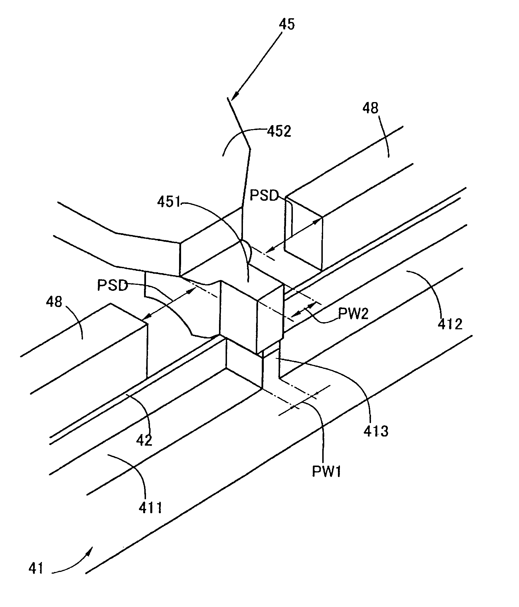
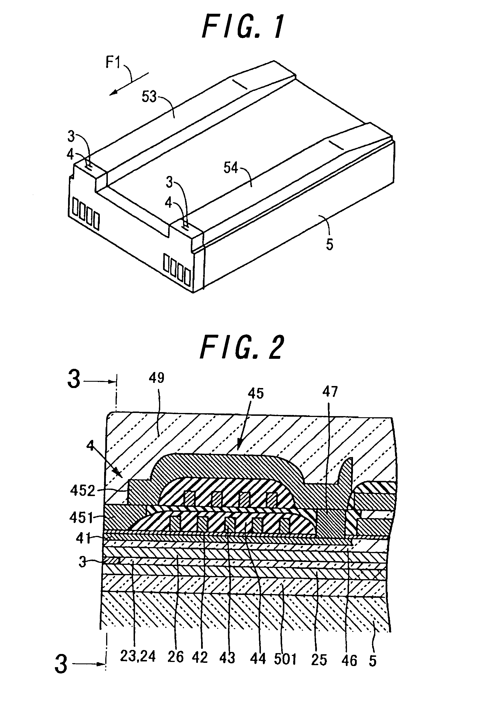
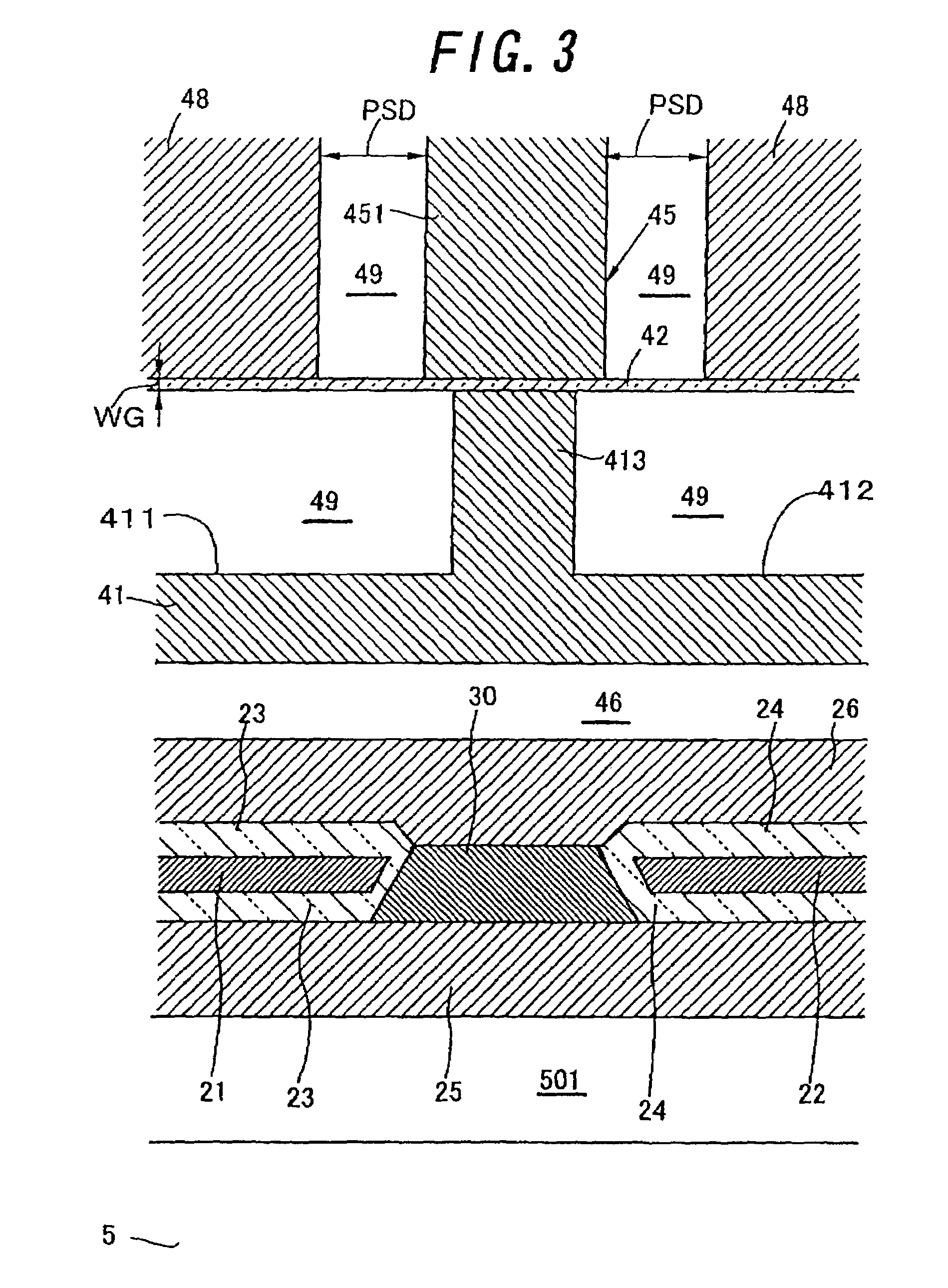
[0039]FIG. 1 is a perspective view showing a thin film magnetic head according to the present invention, and FIG. 2 is an enlarged cross sectional view showing the thin film magnetic head in FIG. 1. FIG. 3 is an enlarged cross sectional view showing the thin film magnetic head in FIG. 2, taken on line “3—3”, and FIG. 4 is an enlarged plan view showing the writing element of the thin film magnetic head in FIGS. 1–3, and FIG. 5 is an enlarged perspective view showing the pole portions of the thin film magnetic head in FIGS. 1–4. In this embodiment, a composite type thin film magnetic head, comprised of a writing element 4 and a reading element 3, is shown. The writing element 4 and the reading element 3 are formed on a base 5 to be employed as a slider, and the forefronts of the elements 3 and 4 are located at the air bearing surfaces (hereinafter, called as “ABS”s) 53 and 54 of the thin film magnetic head, respectively, which are opposite to a magnetic recor...


PUM


Abstract

A first magnetic film includes a first pole piece, and a second magnetic film includes a second magnetic piece. A gap film is disposed between the first pole piece and the second pole piece. The first magnetic film and the second magnetic film are magnetically joined with each other at a joint as viewed backward from the first pole chip and the second pole chip. A coil film winds vertically around the joint. Third magnetic films are disposed at both sides of the first pole piece or the second pole piece by a given distance.

Description

BACKGROUND OF THE INVENTION[0001]1. Field of the Invention[0002]This invention relates to a thin film magnetic head, a magnetic head device and a magnetic recording / reproducing device.[0003]2. Related Art Statement[0004]A composite type magnetic head comprised of a writing element and a reading element with a giant magnetoresistive effective film (hereinafter, called as a “GMR film”) is employed as a thin film magnetic head to be utilized in a magnetic disk drive device of a computer memory unit.[0005]As the writing element is employed an inductive type electromagnetic conversion element, which is formed on the reading element. The inductive type electromagnetic conversion element is comprised of a bottom magnetic film, a top magnetic film, a coil film supported by a gap film and an insulating film and the like.[0006]The forefronts of the bottom magnetic film and the top magnetic film are composed of a bottom pole piece and a top pole piece, respectively, which are opposed to each o...

Claims


Application Information

Patent Timeline
IPC IPC(8): G11B5/147G11B5/31G11B5/39
CPCB82Y10/00B82Y25/00G11B5/3116G11B5/313G11B5/3967G11B2005/3996G11B5/3153G11B5/312
Inventor YAMANAKA, NOBORU
Owner TDK CORPARATION
Why Eureka
Try Eureka