
Diesel Particulate Filter Performance Using Sonic Particle Agglomeration

a technology of sonic particle agglomeration and diesel engine, which is applied in the direction of liquid degasification, auxillary pretreatment, separation process, etc., can solve the problems of low gaseous emissions of unburned hydrocarbon and carbon monoxide, the in-cylinder design changes have not been able to meet the emission limits of these engines, and the engine is currently subject to strict emission limits

Active Publication Date: 2007-10-04
SOUTHWEST RES INST
View PDF20 Cites 9 Cited by
  • Summary
  • Abstract
  • Description
  • Claims
  • Application Information

AI Technical Summary

Benefits of technology

[0012] To meet European standards, it is customary for engine manufacturers to advance injection timing. This increases engine-out nitric oxide emissions, but reduces engine-out particulate matter emissions. The reductions in particulate emissions are usually sufficient to allow the use of flowthrough DPF's despite their reduced efficiency. Increases in nitric oxide emissions may be handled by urea-selective catalytic reduction devices. Using this approach to emissions control, the vehicle manufacturer offers an improved fuel economy due to the advanced injection timing as well as the lower back pressure filter characteristic.

Problems solved by technology

Internal combustion engines used for mobile or stationary applications are currently subject to strict emission limits.
In-cylinder design changes have fallen short of allowing these engines to meet these emissions limits.
In diesel engines, especially those that are classified as heavy-duty, gaseous emissions of unburned hydrocarbon and carbon monoxide are extremely low due to the lean burn nature of diffusion combustion.
However, both nitric oxide and particulate matter emissions present a challenge to engineers.
The challenge for catalytically treating and reducing nitric oxide is presented due to the excess oxygen in the exhaust of a typical diesel engine.
The challenge of reducing particulate matter results from the nature of diffusion combustion.
However, a penalty associated with such high filtration efficiency is high exhaust system restriction.
This exhaust restriction increases as trapping continues, and generally adversely impacts engine performance and fuel economy.
As compared to wallflow filters, flowthrough filters have less exhaust restriction, but are also less efficient.

Method used


Image

  • Diesel Particulate Filter Performance Using Sonic Particle Agglomeration
  • Diesel Particulate Filter Performance Using Sonic Particle Agglomeration
  • Diesel Particulate Filter Performance Using Sonic Particle Agglomeration

Examples


Embodiment Construction

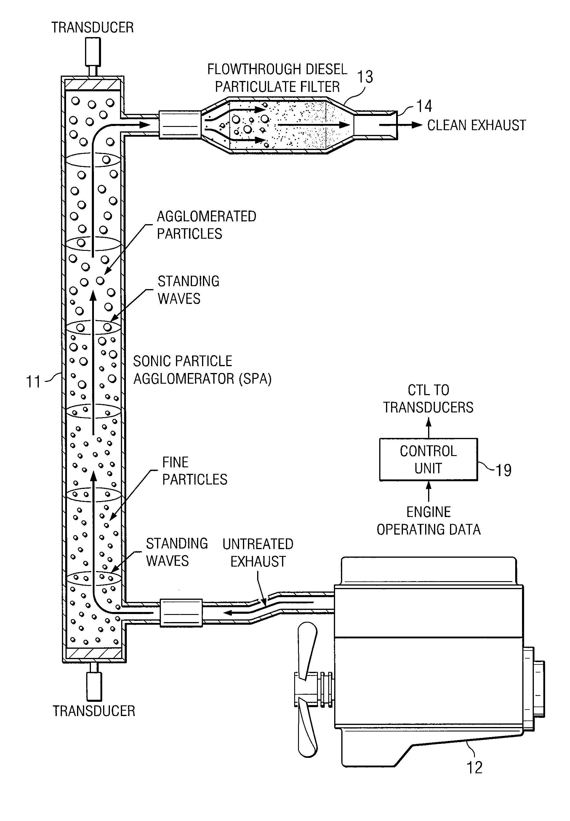
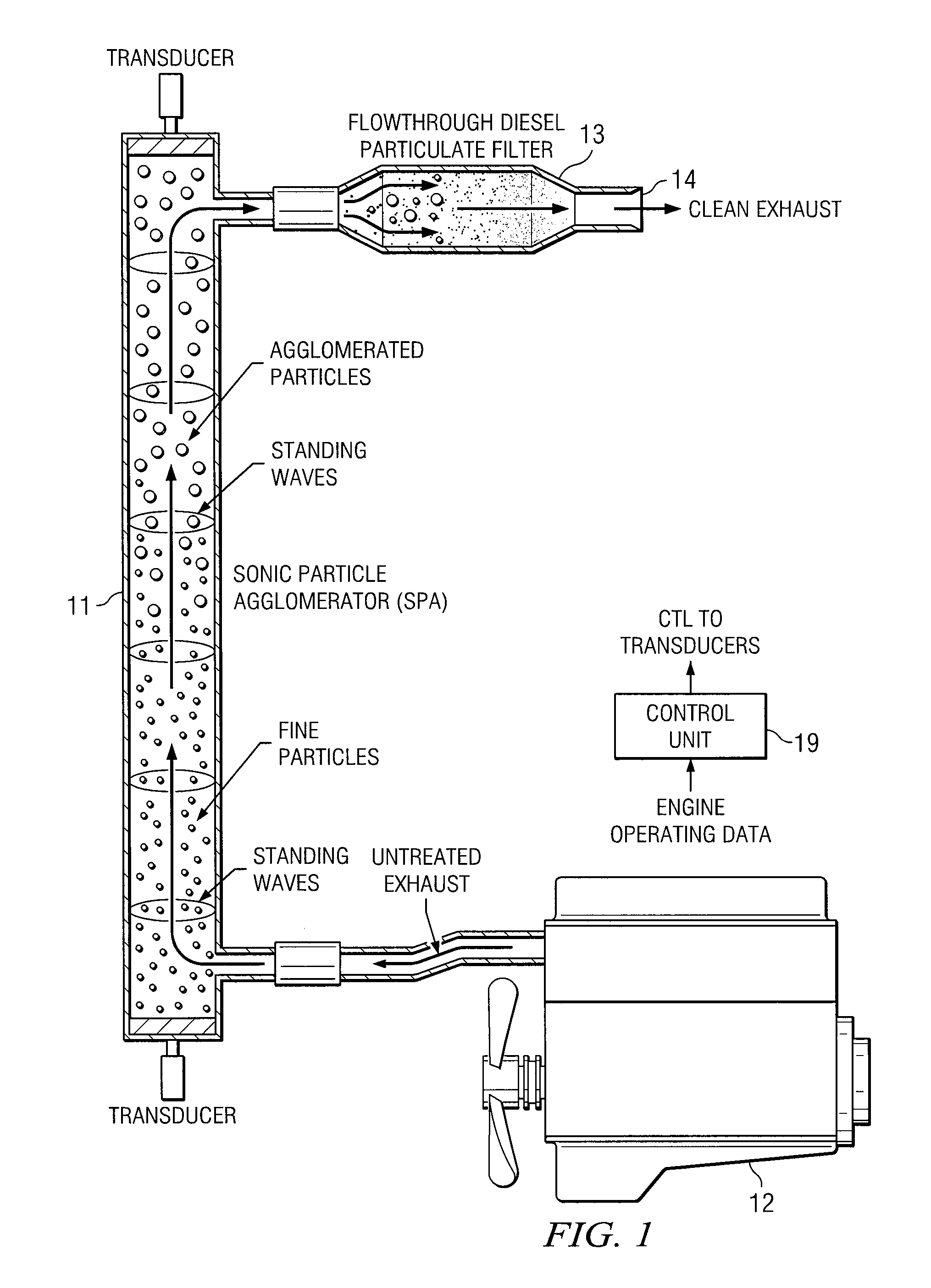
[0010] As stated in the Background, an advantage of flowthrough diesel particulate filters (DPF's) is their low back pressure characteristic. This characteristic is a result of the fact that DPF's cause less restriction to engine exhaust. It follows that they do not present the same adverse impact on engine performance or fuel economy as do wallflow DPF's.

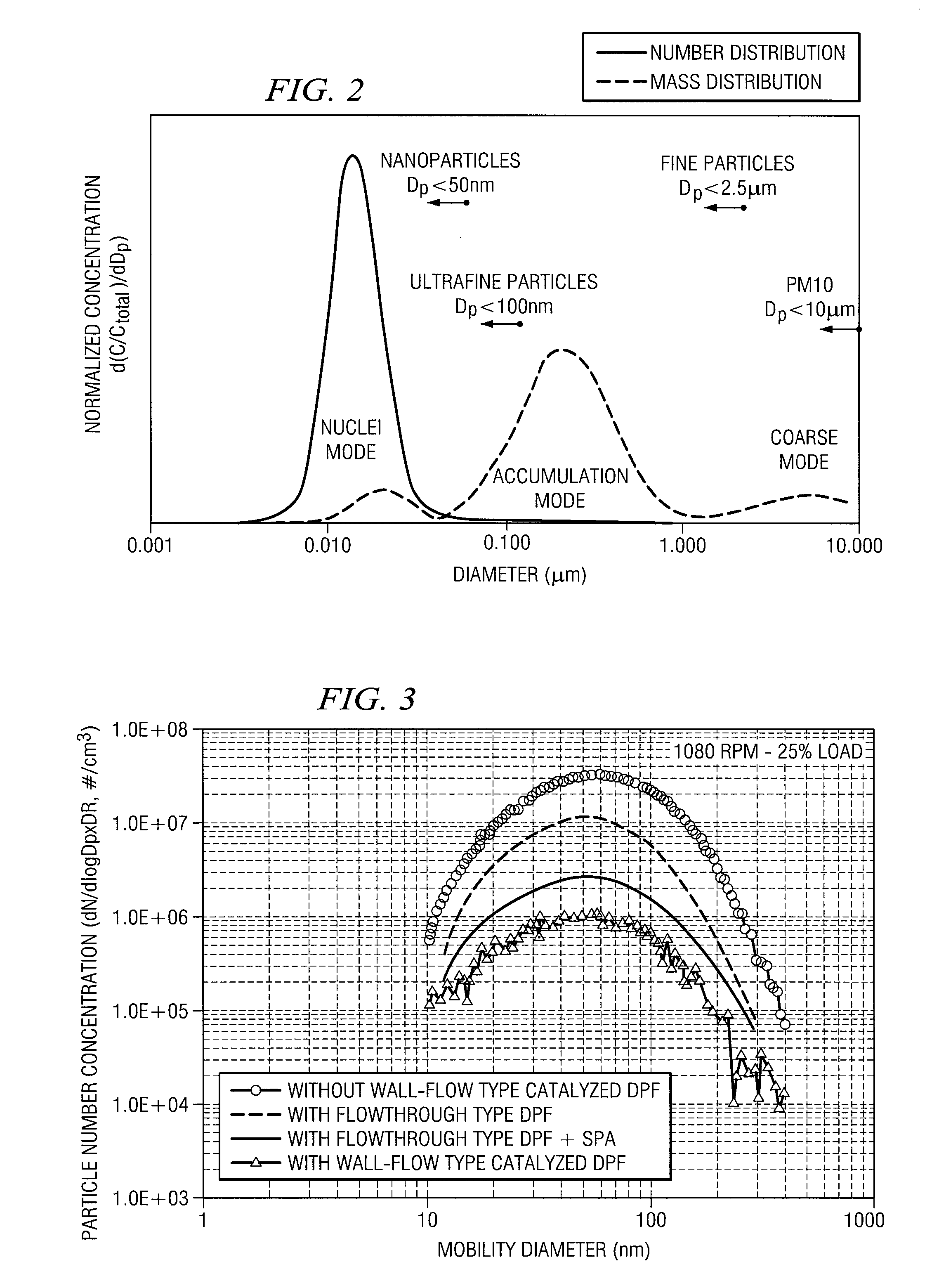
[0011] On the other hand, the filtration efficiency of flowthrough DPF's is rather low (about 50 percent). This fact has limited the application of flowthrough DPF's to either retrofit applications or to vehicles that must meet only less stringent European particulate emissions standards.

[0012] To meet European standards, it is customary for engine manufacturers to advance injection timing. This increases engine-out nitric oxide emissions, but reduces engine-out particulate matter emissions. The reductions in particulate emissions are usually sufficient to allow the use of flowthrough DPF's despite their reduced efficiency. Incre...


PUM

PropertyMeasurementUnit
Lengthaaaaaaaaaa
Mechanical propertiesaaaaaaaaaa
Power consumptionaaaaaaaaaa

Abstract

A method and system for improving the performance of diesel particulate filters. Before entering the filter, the exhaust gas is subjected to sonic waves to agglomerate the particles.

Description

RELATED PATENT APPLICATION [0001] This application claims the benefit of U.S. Provisional Application No. 60 / 777,600, filed Feb. 28, 2006 and entitled “Improved Diesel Particulate Filter Performance Using Sonic Particle Agglomeration.”TECHNICAL FIELD OF THE INVENTION [0002] This invention relates to reduction of emissions from diesel engines, and more particularly to improving the performance of diesel particulate filters. BACKGROUND OF THE INVENTION [0003] Internal combustion engines used for mobile or stationary applications are currently subject to strict emission limits. In-cylinder design changes have fallen short of allowing these engines to meet these emissions limits. Technology advances in the catalyst field have made it possible for integrated systems of engine and exhaust treatment to achieve extremely low emissions. Even so, more emission reduction efficiencies are sought from existing systems and new catalytic reduction solutions are needed to achieve even lower emissio...

Claims


Application Information

Patent Timeline
IPC IPC(8): F01N3/00F01N3/02
CPCF01N3/021F01N3/033F01N13/009F01N2250/08Y02T10/20F01N3/037Y02T10/12
Inventor KHAIR, MAGDI KAISERTREUHAFT, MARTIN B.ABDUL-KHALEK, IMAD S.
Owner SOUTHWEST RES INST
Learn More