Thin film magnetic head

Active Publication Date: 2006-09-21
TDK CORPARATION
View PDF5 Cites 7 Cited by
  • Summary
  • Abstract
  • Description
  • Claims
  • Application Information

AI Technical Summary

Benefits of technology

[0010] In the thin film magnetic head according to the present invention, the hard magnetic layer is located between the pair of magnetic shield layers. For this reason, a static magnetic field generated from the hard magnetic layer acts on each magnetic shield layer. Therefore, where the magnetization direction of the magnetic domain in the magnetic shield layer is opposite to a direction of the static magnetic field by the hard magnetic layer, this state is disadvantageous in terms of magnetic energy and thus results in decreasing the region of the magnetic domain with the magnetic moment opposite to the static magnetic field. On the other hand, where the magnetization direction of the magnetic domain in the magnetic shield layer is the same as the direction of the static magnetic field by the hard magnetic layer, this state is advantageous in terms of magnetic energy and thus results in increasing the region of the magnetic domain with the magnetic moment in the same direction as the static magnetic field. In this configuration, the hard magnetic layer is located on the second end face side opposite to the first end face forming the medium-facing surface of the magnetic shield layers and the length of the hard magnetic layer in the direction perpendicular to the first end face is larger than ⅓ and smaller than ½ of the length of the magnetic shield layers between the first end face and the second end face. For this reason, an approximately half region on the second end face side in the magnetic shield layers comes to have the same direction as the direction of the static magnetic field generated from the hard magnetic layer, and the number of magnetic domains in the magnetic shield layers is likely to become approximately 4. Therefore, it becomes easier to maintain the domain structure of the magnetic shield layers as the 4-domain structure with extremely small magnetic energy, which can suppress the transition of the domain structure in the magnetic shield layers and thus stabilize the domain structure. In consequence, it becomes feasible to achieve adequate reduction of the Barkhausen noise. Since in the thin film magnetic head of the present invention the hard magnetic layer is located on the second end face side of the magnetic shield layers, the static magnetic field generated from the hard magnetic layer causes little direct influence on the magnetization direction of the free layer in the magnetoresistive effect element located on the first end face side of the magnetic shield layers.
[0022] The present invention successfully provides the thin film magnetic head capable of stabilizing the domain structure of the magnetic shield layers and achieving adequate reduction of the Barkhausen noise.

Problems solved by technology

Therefore, where the magnetization direction of the magnetic domain in the magnetic shield layer is opposite to a direction of the static magnetic field by the hard magnetic layer, this state is disadvantageous in terms of magnetic energy and thus results in decreasing the region of the magnetic domain with the magnetic moment opposite to the static magnetic field.

Method used


Image

  • Thin film magnetic head
  • Thin film magnetic head
  • Thin film magnetic head

Examples


first embodiment

[0050] (Configuration of Thin Film Magnetic Head)

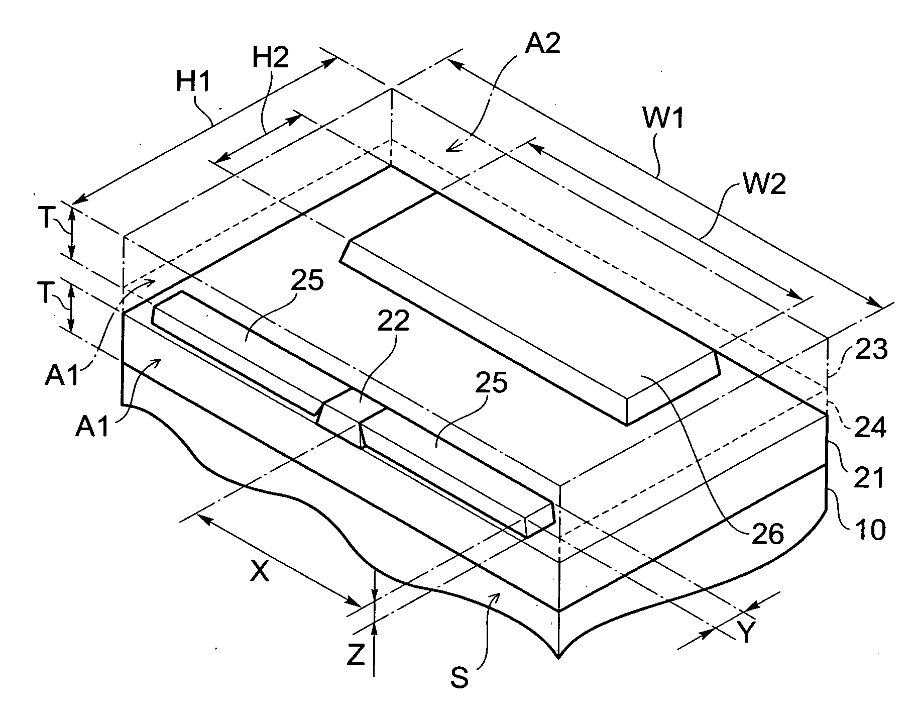
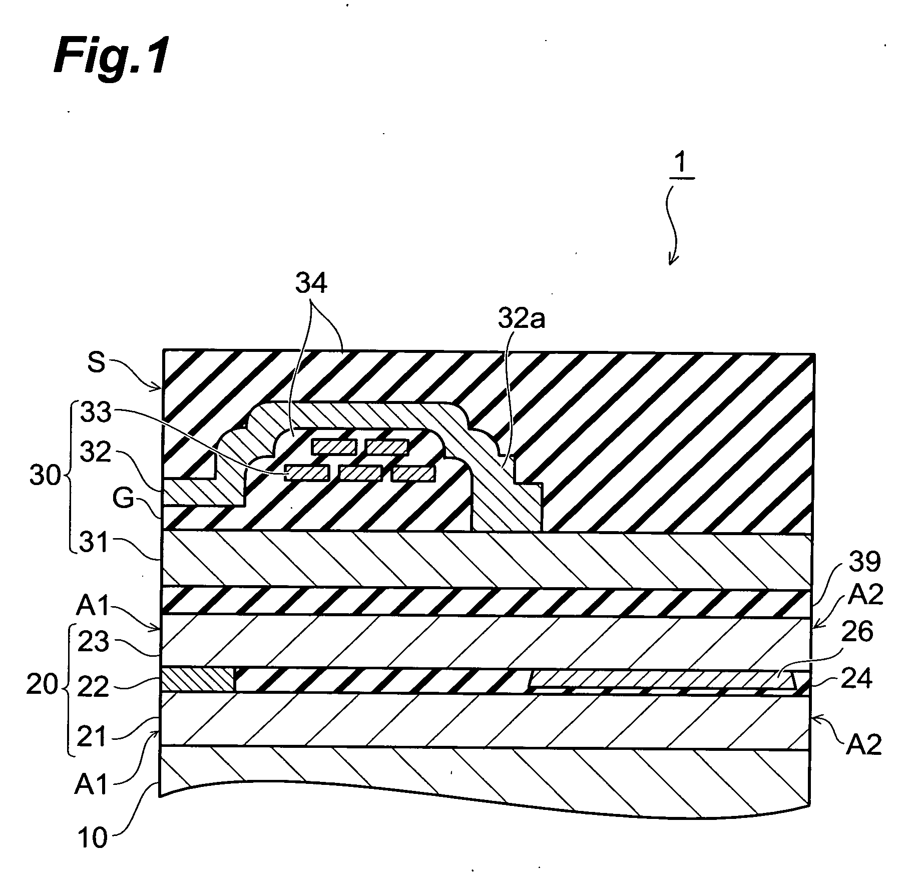
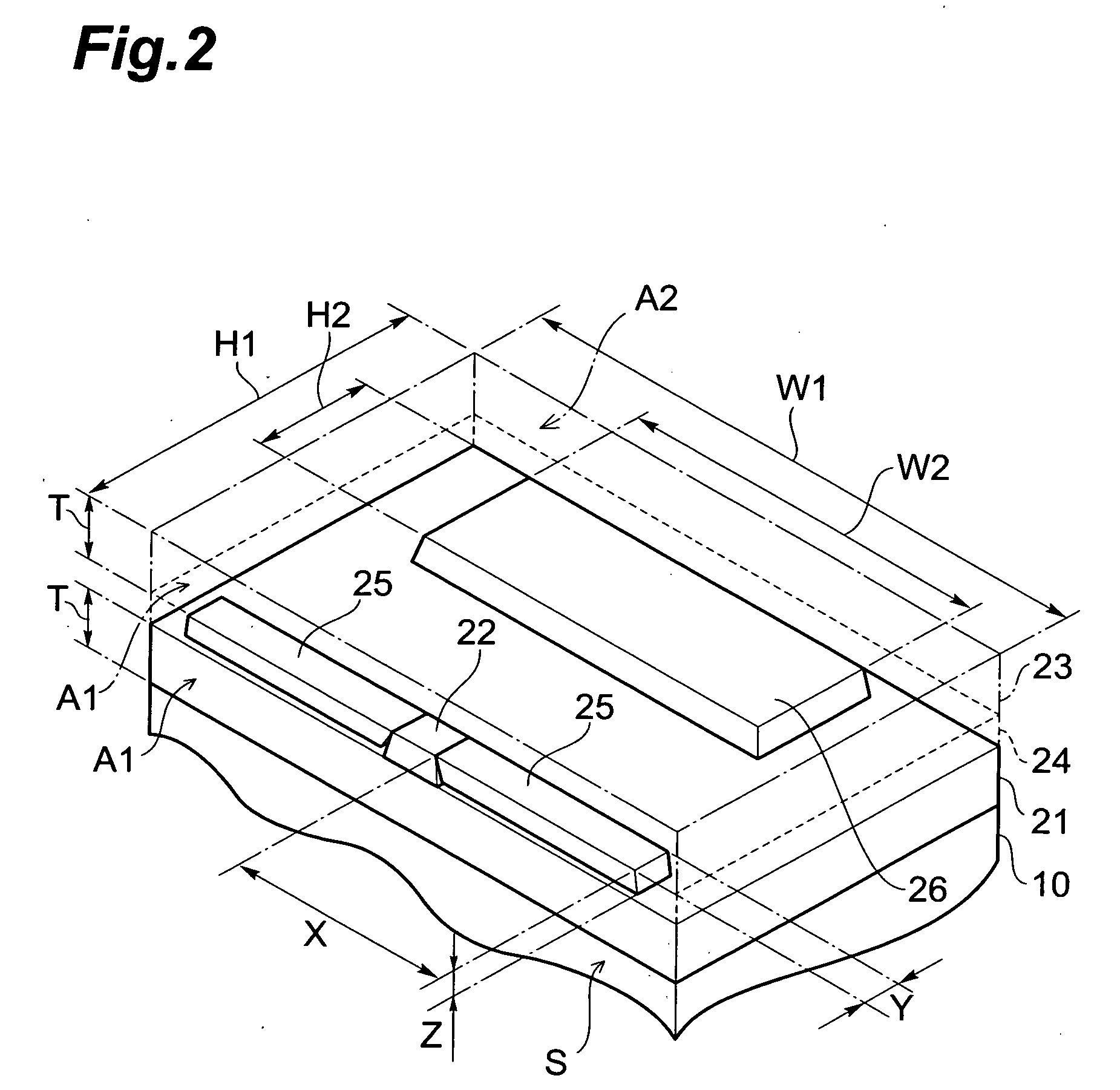
[0051] A configuration of thin film magnetic head 1 according to the first embodiment will be described with reference to FIGS. 1 and 2. FIG. 1 is a schematic sectional view of the thin film magnetic head taken along a direction normal to a medium-facing surface (also called an air bearing surface (ABS: AirBearing Surface)) of the thin film magnetic head according to the first embodiment and viewed from the track width direction. FIG. 2 is a perspective view showing a part of the thin film magnetic head according to the first embodiment.

[0052] The thin film magnetic head 1 is provided over a base 10 and forms a part of an unrepresented magnetic head slider. The thin film magnetic head 1 is a composite thin film magnetic head in which a reproducing head portion 20 having an after-described MR (magnetoresistance effect: MagnetoResistive) element 22, an insulating layer 39, and a recording head portion 30 as an induction type electroma...

example 1

[0085] In Example 1, the base 10 was formed by depositing the ground layer of Al2O3 on the substrate of Al2O3.TiC, and thereafter the magnetic shield layers 21, 23, MR layer 22, bias-applying layers 25, and hard magnetic layer 26 were formed according to the aforementioned production method of the thin film magnetic head 1. The magnetic shield layers 21, 23 were made of NiFe and had the width W1 of 90 μm the height H1 of 25 μm, and the thickness T of 2.0 μm. The bias-applying layers 25 were made of CoCrPt and had the width X of 14 μm and the depth Y of 3.5 μm. The hard magnetic layer 26 was made of CoCrPt and had the width W2 of 50 μm and the height H2 of 10 μm.

second embodiment

[0095] Next, a configuration of thin film magnetic head 100 according to the second embodiment will be described with reference to FIGS. 13 and 14. FIG. 13 is a schematic sectional view of the thin film magnetic head taken along a direction normal to the medium-facing surface of the thin film magnetic head according to the second embodiment and viewed from the track width direction. FIG. 14 is a perspective view showing a part of the thin film magnetic head according to the second embodiment. The thin film magnetic head 100 of the second embodiment is different from the thin film magnetic head 1 of the first embodiment in that the thin film magnetic head 100 further comprises an insulating film 24c. The thin film magnetic head 100 of the second embodiment will be described below with focus on the difference, without redundant description.

[0096] The insulating film 24c is formed so as not to cover the top surface of the MR element 22 and so as to cover the top surface of the hard ma...


PUM


Abstract

A thin film magnetic head has an air bearing surface and comprises magnetic shield layers, an MR element, bias-applying layers, and a hard magnetic layer. Each of the magnetic shield layers has an end face forming the air bearing surface, and an end face located opposite to the end face. The MR element is located between the magnetic shield layers and on the end face side. The bias-applying layers are located between the magnetic shield layers and are arranged to apply a bias magnetic field to the MR element. The hard magnetic layer is located between the magnetic shield layers and on the end face side. A height of the hard magnetic layer is larger than ⅓ and smaller than ½ of a height of each magnetic shield layer.

Description

BACKGROUND OF THE INVENTION [0001] 1. Field of the Invention [0002] The present invention relates to a thin film magnetic head. [0003] 2. Related Background Art [0004] An example of the known thin film magnetic heads for reading magnetic information in magnetic media such as hard disks is a thin film magnetic head comprising a magnetoresistive effect element (hereinafter referred to as an MR (MagnetoResistive) element), and magnetic shield layers provided through a nonmagnetic insulating layer on both upper and lower sides of the MR element (e.g., Japanese Patent Application Laid-Open No. 9-288806) [0005] Incidentally, there are demands for decrease of Barkhausen noise as a property of a reproducing head included in the thin film magnetic head. [0006] An object of the present invention is therefore to provide a thin film magnetic head capable of achieving adequate reduction in Barkhausen noise. SUMMARY OF THE INVENTION [0007] The Barkhausen noise appears in a magnetic signal of the ...

Claims


Application Information

Patent Timeline
IPC IPC(8): G11B5/33G11B5/127
CPCG11B5/3932G11B5/3967
Inventor OHTA, NAOKISATO, KAZUKIKASAHARA, NORIAKIKAGAMI, TAKEO
Owner TDK CORPARATION
Why Eureka
Try Eureka