Magnetic resonance imaging device and gradient magnetic field coil used for it

a magnetic field coil and magnetic resonance imaging technology, applied in the field of magnetic resonance imaging, can solve the problems of mechanical distortion and vibration, affecting the image quality of fixed objects, so as to reduce the noise caused by vibration, prevent the effect of deterioration of image quality and effective suppression of vibration

Inactive Publication Date: 2005-08-23
HITACHI LTD
View PDF2 Cites 42 Cited by
  • Summary
  • Abstract
  • Description
  • Claims
  • Application Information

AI Technical Summary

Benefits of technology

[0027]By directly fixing the gradient magnetic field coil to a yoke unit having a large mass, the vibration of the coil is suppressed, and thus the noise caused by this vibration can be reduced. Since the mass of the yoke unit is generally considerably larger than that of the static magnetic field generating magnet, the vibration of the gradient magnetic field is not transmitted to the static magnetic field generating magnet. Thus, the vibration propagated through fixed objects can be effectively suppressed, and the effect that the vibration has on the static magnetic field generating magnet, that is, fluctuation of the static magnetic field and resultant deterioration of the image quality, can be prevented. Further, since the yoke is placed on both sides of the static magnetic field generating magnet, the gradient magnetic field coil can be fixed without providing a special space on the magnet-installing floor or the sides of the apparatus. Thereby, the MR-interventional procedure can be performed unhindered by the structure of the apparatus.

Problems solved by technology

However, in the MRI apparatus of this type, the object to be examined is placed in a space like a tunnel, imparting an oppressive feeling to the object.
It is also known that such a condition causes fear in a claustrophobic person and children.
However, an electromagnetic force works on the gradient magnetic field coil when current for driving the gradient magnetic field is applied in pulse form, and so mechanical distortion and vibration tend to occur, and this vibration is transmitted to the magnet for generating the static magnetic field.
Thus, some problems occur in that the uniformity of the magnetic field in the measurement space is deteriorated and the acoustic noise due to the vibration of the gradient magnetic field coil is increased.
The above-mentioned problems are far more serious in an MRI apparatus having an open-gantry structure.
That is, the open MRI apparatus is more liable to be affected by vibration than an apparatus employing a tunnel type magnet.
The vibration transmitted from the gradient magnetic field coil to the magnet deteriorates the stability of the static magnetic field generated by said magnet, and thus the image quality is deteriorated.
Further, as described above, both noise and vibration increase during high-speed imaging in real time, since the gradient magnetic field coil is subject to a rapid switching-drive.
However, in spite of the amount of noise reduction, those methods have created some other problems, that is, the weight of the gradient magnetic field coil is increased and the control procedure becomes complicated when using those methods.
However, it is difficult to apply this method to an open MRI apparatus; that is, in the open MRI apparatus, the gradient magnetic field coil is divided into an upper part and a lower part, and they are arranged near the facing plane of the magnet.
An MRI apparatus has problems of reducing vibration and noise of the gradient magnetic field coil, as well as of reducing eddy currents generated on the surface of the magnet vessel placed near the gradient magnetic field coil when the pulse current is transmitted to said coil.
This effect causes a variance in the amount of the gradient magnetic field which must be applied and interferes with execution of the high-speed imaging.

Method used


Image

  • Magnetic resonance imaging device and gradient magnetic field coil used for it
  • Magnetic resonance imaging device and gradient magnetic field coil used for it
  • Magnetic resonance imaging device and gradient magnetic field coil used for it

Examples


first embodiment

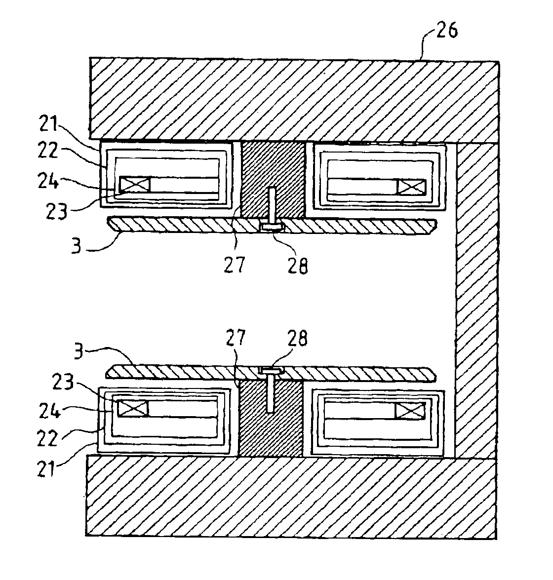
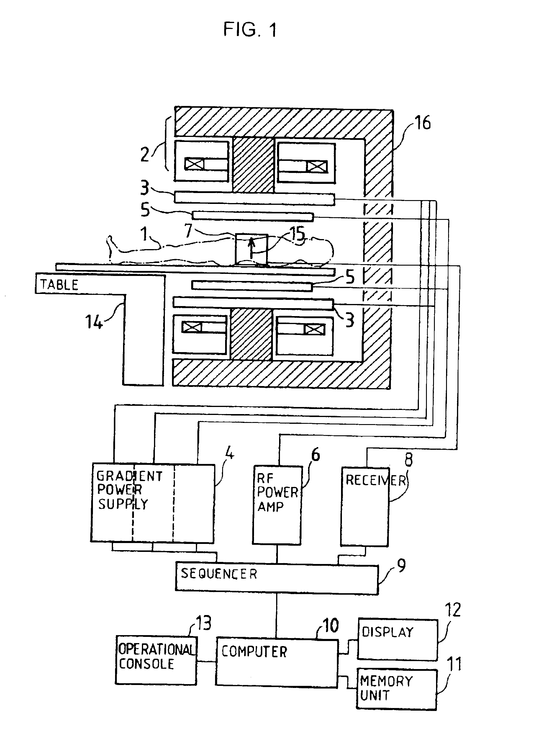
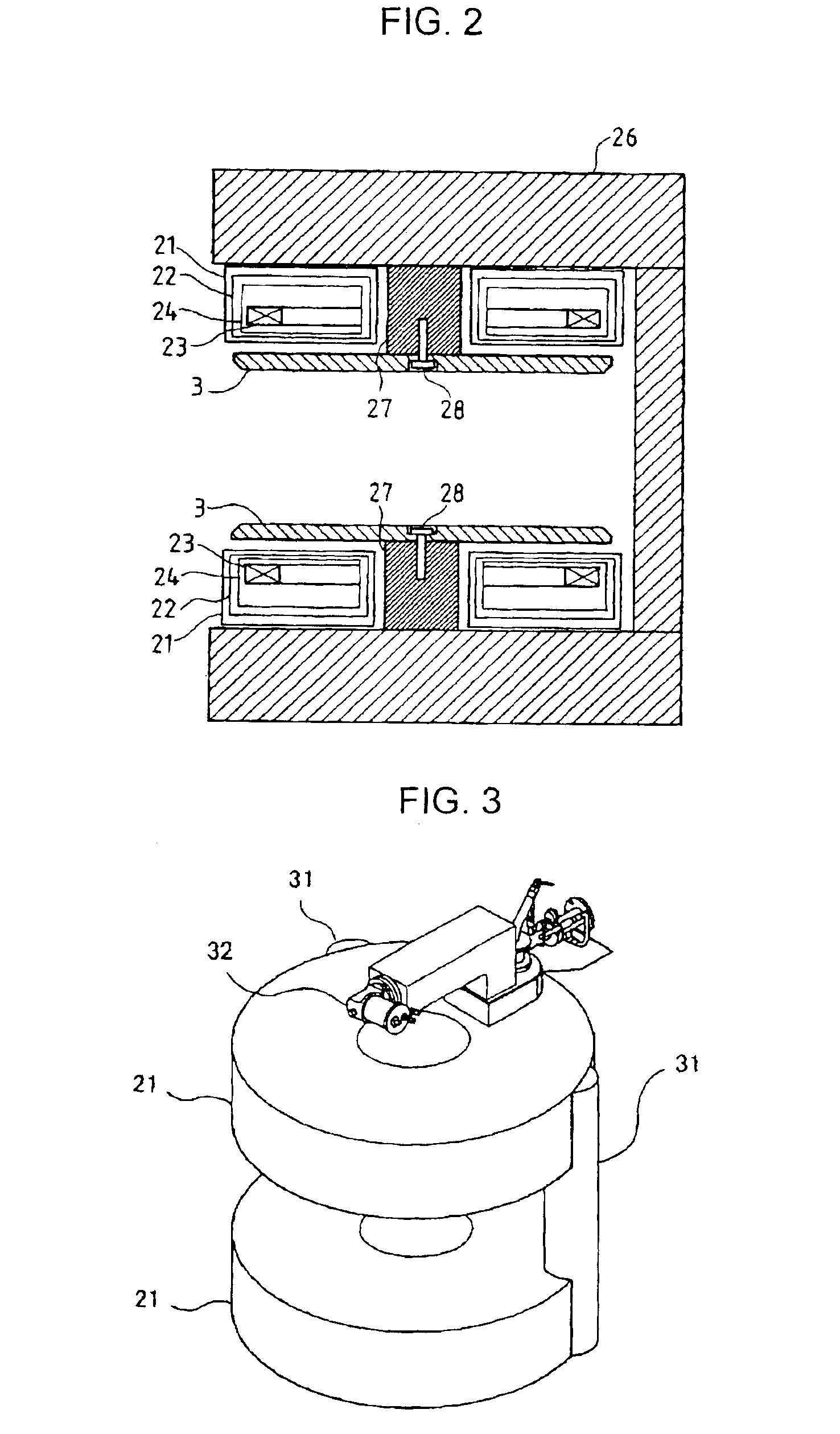
[0073]FIG. 2 shows in more detail the structure of the static magnetic field generating magnet 2 and the gradient magnetic field coils 3 of the open MRI shown in FIG. 1 according to the present invention.

[0074]First, the structure of the static magnetic field generating magnet 2 will be described in detail. The static magnetic field generating magnet 2 comprises a pair of static magnetic field generating coils, upper and lower, disposed in doughnut-shaped cryostats 21. Liquid helium tanks 24 surrounded by thermal shield plates 22 are placed within the cryostats 21, and superconductive coils 23 are disposed in the liquid helium tanks 24. The inside of the cryostats 21 are evacuated so as to maintain the low temperature of the liquid helium. The liquid helium tanks 24 and the thermal shield plates 22 are supported by adiathermic wires (not shown) for preventing outside heat from entering, so as to reduce evaporation of the liquid helium. Incidentally, although only single thermal shie...

second embodiment

[0086]Next, the support structure of the gradient magnetic field coil in the present invention will be described.

[0087]FIG. 7 shows an open MRI apparatus according to the second embodiment. All of the structure, except for the installation structure of the static magnetic field generating magnets 2 and the gradient magnetic field coils 3, is the same as that shown in FIG. 2, and so the common structure is omitted in FIG. 7.

[0088]In the second embodiment, the static magnetic field generating magnet 2 is also a superconductive magnet. The structure of it is generally the same as that in the first embodiment, being comprised of a pair of upper and lower cryostats 71, thermal shield plates 72 within said cryostats 71, and liquid helium tanks 74 containing the superconductive coils 73. Plural thermal shield plates 72 may be provided in the same way as in the first embodiment, and plural superconductive coils 73 may be also installed. Further, the iron yoke 26, comprising a magnetic circu...

fourth embodiment

[0093]Next, the support structure of the gradient magnetic field coils in the MRI apparatus will be described with reference to FIGS. 9 and 10. FIG. 9 is a vertical section of the static magnetic field generating magnet, and FIG. 10 is its top view. This embodiment is different from the above-described three embodiments in the following points: The gradient magnetic field coil supporter is comprised of a first gradient magnetic field coil supporter of cylindrical shape and a second gradient magnetic field coil supporter of plate shape. The center of the gradient magnetic field coil 3a, which is arranged above the measurement space 25, is joined with the first cylindrical gradient magnetic field coil supporter 101a arranged within the air space provided in the center of the upper cryostat 21a, and thus the gradient magnetic field coil 3a is supported. The upper end of the first gradient magnetic field coil supporter 101a is joined with the center part of the second gradient magnetic...


PUM


Abstract

To reduce vibration and noise generated in supplying pulsatile current to the gradient magnetic field coil for driving that coil in a MRI apparatus, an active shielded gradient magnetic field coil is used, in which the gradient magnetic field coil is supported by and fixed to the static magnetic field generating magnet. The supporter for supporting this gradient magnetic field coil in non-contact does not prevent the interventional procedure performed by a doctor. Further, an eddy current generated on the surface of the static magnetic field generating magnet near the periphery of the gradient magnetic field coil, when supplying the pulsatile current to the gradient magnetic field coil, can be reduced.

Description

FIELD OF THE INVENTION[0001]The present invention relates to a magnetic resonance imaging (hereinafter referred to as a MRI) apparatus and to a gradient magnetic field coil for use in said MRI apparatus. More particularly, it relates to an MRI apparatus employing an open magnet, which does not give an oppressive feeling to an object to be examined, and which provides the object comfortable conditions for examination by reducing noise. The invention further relates to a gradient magnetic field coil constructed so as to reduce eddy currents generated on the surface of the vessel of a magnet for generating a static magnetic field when current is applied to the gradient magnetic field coil to perform imaging of the object.BACKGROUND OF THE INVENTION[0002]In an MRI apparatus, a magnet has been conventionally employed for generating a static magnetic field, the magnet comprising a narrow tubular solenoid coil, which can efficiently generate a uniform static magnetic field. However, in the...

Claims


Application Information

Patent Timeline
Patent Type & Authority Patents(United States)
IPC IPC(8): G01R33/385G01R33/38G01R33/28G01R33/421
CPCG01R33/3806G01R33/385G01R33/3854G01R33/4215G01R33/3856
Inventor TSUDA, MUNETAKATAKESHIMA, HIROTAKAYATSUO, TAKESHI
Owner HITACHI LTD
Why Eureka
Try Eureka