Radio frequency diplexer

a frequency diplexer and radio frequency technology, applied in the field of radio frequency diplexers, can solve the problems of increasing the distance between the inner conductor and the outer conductor, increasing the cost, and increasing the cost of the device, so as to shorten the distance between the inner conductor and the effect of strong coupling

Inactive Publication Date: 2005-08-23
KATHEIN WERKE KG
View PDF13 Cites 15 Cited by
  • Summary
  • Abstract
  • Description
  • Claims
  • Application Information

AI Technical Summary

Benefits of technology

[0015]Advantageous, space-saving geometric arrangements of the resonator chambers are possible for certain numbers of resonators, but perhaps not for other forms of interconnection. For the purposes of the exemplary illustrative non-limiting implementations, it is thus possible, for example, to provide a frequency diplexer with a total of six resonators, which are arranged in two rows of three each, and in which all three connecting sockets, for the transmitter, for the receiver and for a common port or a common connecting socket (a common transmitting / receiving connecting socket, for example) for connection of an antenna or for the input / output of a common signal path, are located on the same side of the housing. The exemplary illustrative non-limiting implementation makes it possible to provide symmetrical, compact overall geometries.
[0016]Furthermore, one preferred illustrative non-limiting implementation allows particularly strong coupling by considerably shortening the distance between the inner conductors of the relevant resonators.

Problems solved by technology

Both variants have the disadvantage that the tuning process can be carried out only by purely reproducible mechanical manipulations (bending or deformation), and that the tuning of the input to one filter path also influences the electrical behavior of the respective other filter path, and vice versa, so that the two input devices must generally be varied alternately two or more times during the tuning process.
However, in this case as well, the central resonator which is acquired in addition to the resonators in the filter path requires additional space and also results in additional costs, even though it does not significantly contribute to the frequency selectivity of the filter paths.
This avoids the central resonator which is required in the prior art, causes additional costs, and furthermore, also requires even more space.

Method used


Image

  • Radio frequency diplexer
  • Radio frequency diplexer
  • Radio frequency diplexer

Examples


Embodiment Construction

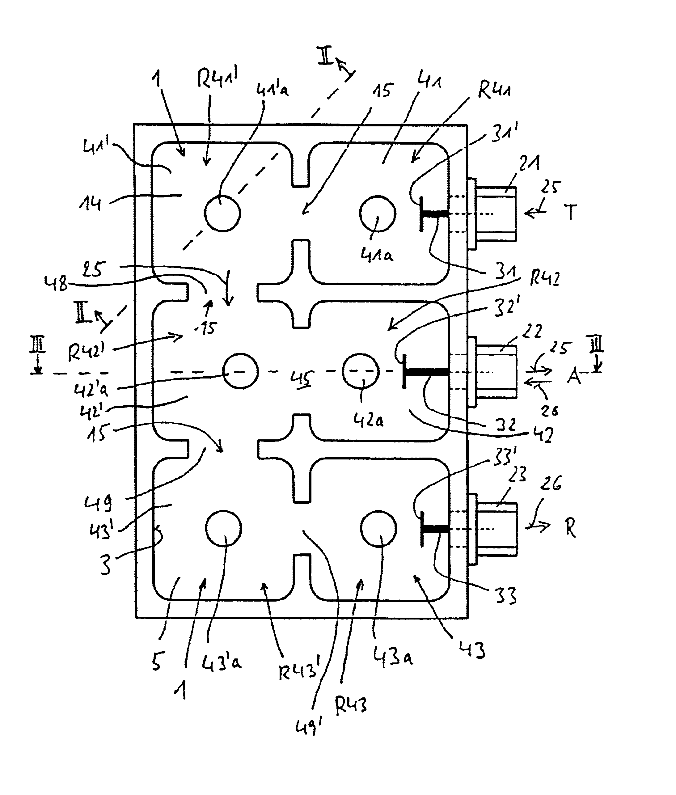
[0024]FIG. 1 shows a schematic horizontal cross section through one preferred non-limiting implementation according to the exemplary illustrative non-limiting diplexer with interconnected radio frequency bandpass filters.

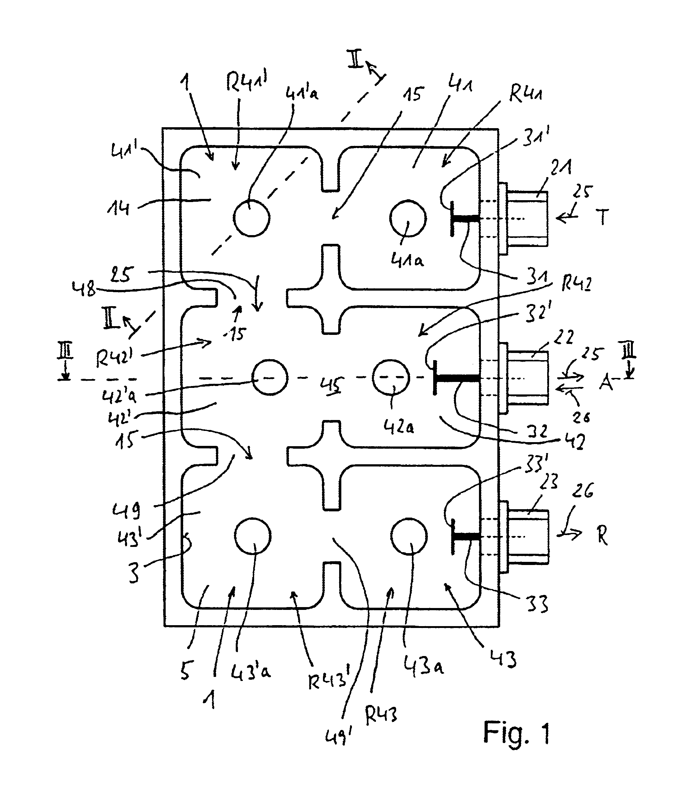
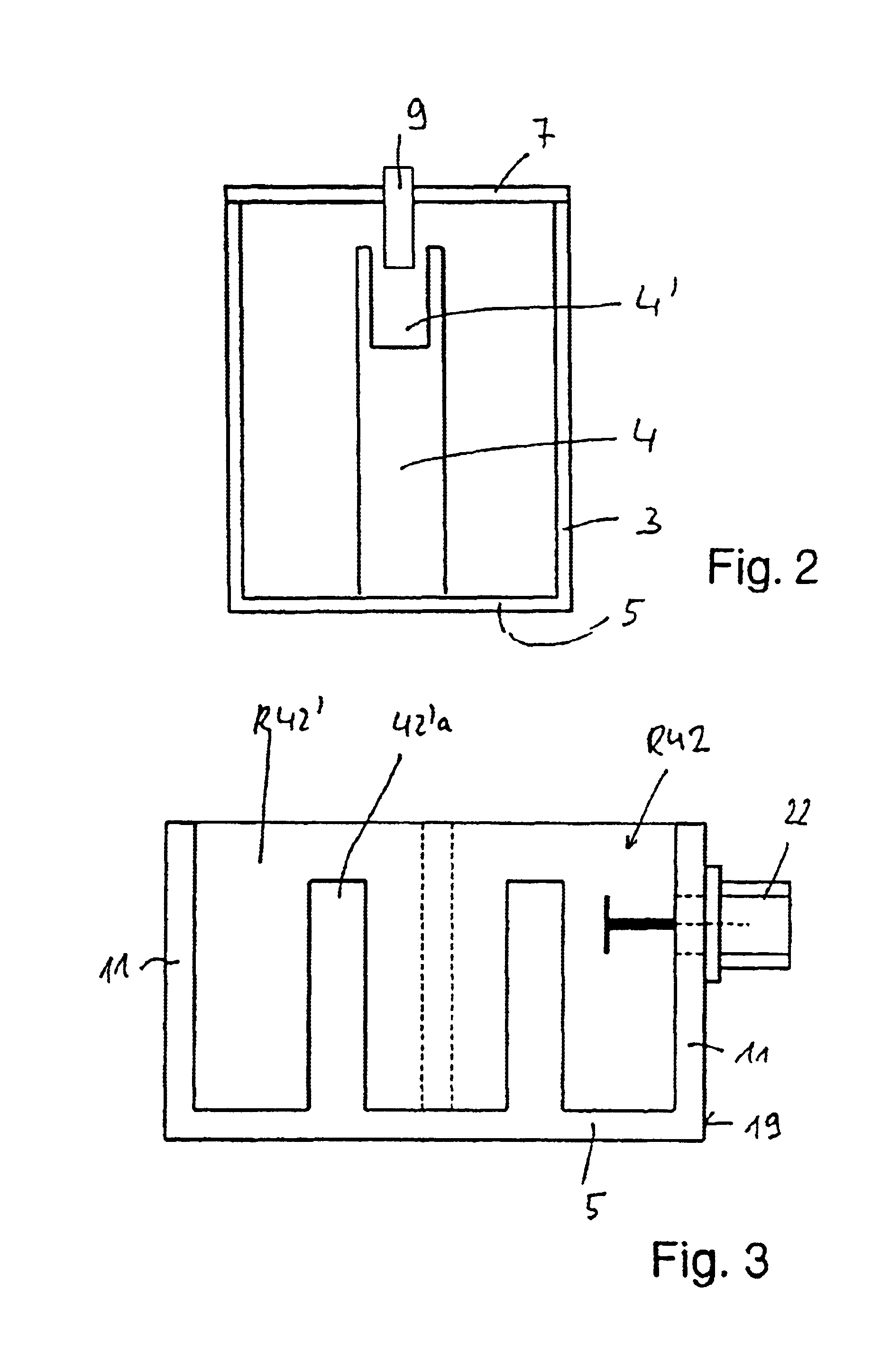
[0025]For this purpose, the exemplary illustrative non-limiting implementation shown in FIG. 1 has six individual circuit radio frequency filters 1, with a coaxial configuration, that is to say six resonators. The configuration of the resonators 1 under discussion is in principle known from EP 1 169 747 B1, to whose complete scope and full content the present application refers. It is also possible to see from this that a single circuit RF filter or single resonator 1 with coaxial configuration in principle comprises an electrically conductive outer conductor 3, an inner conductor 4 which is arranged concentrically or coaxially with respect to it, and a base 5, via which the electrically conductive outer conductor 3 and the electrically inner conductor 4 are electri...


PUM


Abstract

An improved radio frequency diplexer has resonators which are associated either with the transmission path or with the reception path, and at least two additional resonators are also provided. The at least two additionally provided resonators form an interconnection resonator pair which are strongly coupled to one another. Both the transmission path and the reception path are coupled to the second additional resonator, or both the transmission path and the reception path are coupled to the first additional resonator which is provided for inputting to/outputting from the common signal path.

Description

FIELD[0001]The technology herein relates to a radio frequency diplexer in the form of interconnected radio frequency filters.BACKGROUND AND SUMMARY[0002]In radio systems, for example in the mobile radio field, it is often desirable to use a common antenna to transmit and receive signals. The transmission signals and received signals may lie in different frequency bands. The antenna which is used must be suitable for transmitting and receiving both frequency bands. Suitable frequency filtering separates the transmission signals and received signals, ensuring on the one hand that the transmission signals are passed on from the transmitter only to the antenna (not in the direction of the receiver), and on the other hand that the received signals are passed on from the antenna only to the receiver.[0003]A pair of radio frequency filters may be used for this purpose, both of which pass a specific frequency band, namely the respectively desired frequency band (band pass filters). However,...

Claims


Application Information

Patent Timeline
Patent Type & Authority Patents(United States)
IPC IPC(8): H01P1/208H01P7/00H01P1/20H01P7/04H01P7/06
CPCH01P1/208H01P7/04H01P1/2053H01P1/2136H01P7/06H01P1/20H01P1/213
Inventor RATHGEBER, ROLANDWEITZENBERGER, WILHELMSIERACZEWSKI, DIETMAR
Owner KATHEIN WERKE KG
Why Eureka
Try Eureka