Method and apparatus for digital near-end echo/near-end crosstalk cancellation with adaptive correlation

a near-end echo and near-end crosstalk technology, applied in the field of apparatus and methods for signal communication, can solve problems such as signal attenuation, return loss, electromagnetic emission and susceptibility, and can solve the problem of near-end crosstalk interference cancellation and near-end echo interference cancellation

Inactive Publication Date: 2005-08-23
MARVELL ASIA PTE LTD
View PDF25 Cites 63 Cited by
  • Summary
  • Abstract
  • Description
  • Claims
  • Application Information

AI Technical Summary

Benefits of technology

[0043]An object of this invention is to provide a communication transmitting and receiving system in which the effects of near-end echo and near-end crosstalk from the communication medium are mitigated.

Problems solved by technology

These challenges include signal attenuation, echo return loss, crosstalk characteristics of the cable, and electromagnetic emission and susceptibility.
The near-end echo signal degrades the receiver performance to a great extent and is a large source of error in the received signal.

Method used


Image

  • Method and apparatus for digital near-end echo/near-end crosstalk cancellation with adaptive correlation
  • Method and apparatus for digital near-end echo/near-end crosstalk cancellation with adaptive correlation
  • Method and apparatus for digital near-end echo/near-end crosstalk cancellation with adaptive correlation

Examples


first embodiment

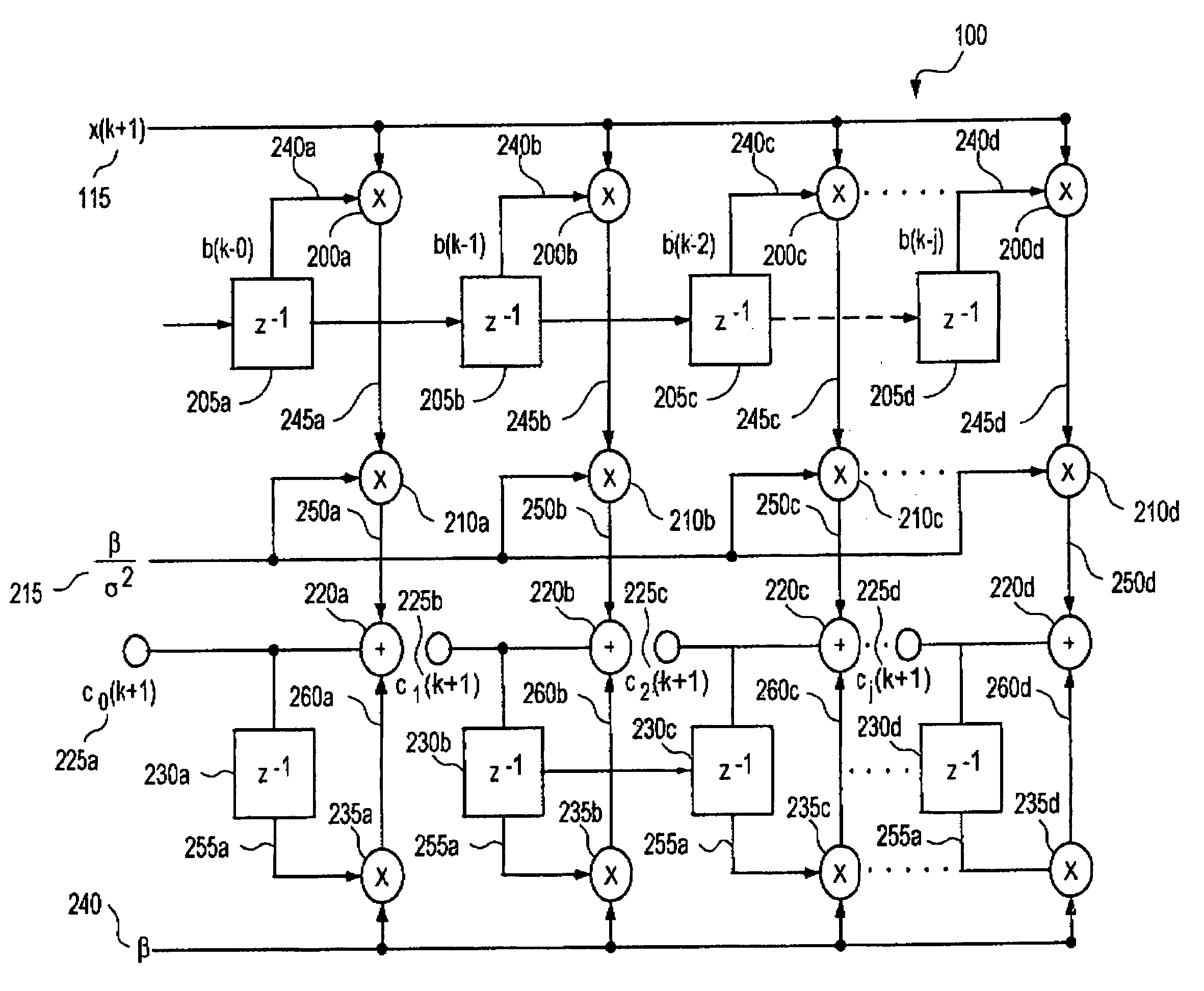
[0070]Refer now to FIG. 5 for a discussion of the correlator 100 circuit of the near-end echo / near-end crosstalk cancellation circuit of this invention. The received signal X(k+1) 115 and the delayed transmitted signals b(k−j) 240a, 240b, 240c, . . . , 240d are the inputs to each of the first multipliers 200a, 200b, 200c, . . . , 200d. The delayed transmitted signals b(k−j) are the outputs of each of the unit delay elements 205a, 205b, 205c, . . . , 205d. The unit delay elements 205a, 205b, 205c, . . . , 205d successively delay the transmitted signal b(k) 120 to form the delayed transmitted signals b(k−j) 240a, 240b, 240c, . . . , 240d.

[0071]The output products 245a, 245b, 245c, . . . , 245d and the first weighting factor (βσ2)

215 are inputs to the second multipliers 210a, 210b, 210c, . . . , 210d. The outputs of the second multipliers 210a, 210b, 210c, . . . , 210d form the weighted products 250a, 250b, 250c, . . . , 250d.

[0072]Each of the new filter coefficients C0 (k+1), . . . ...

second embodiment

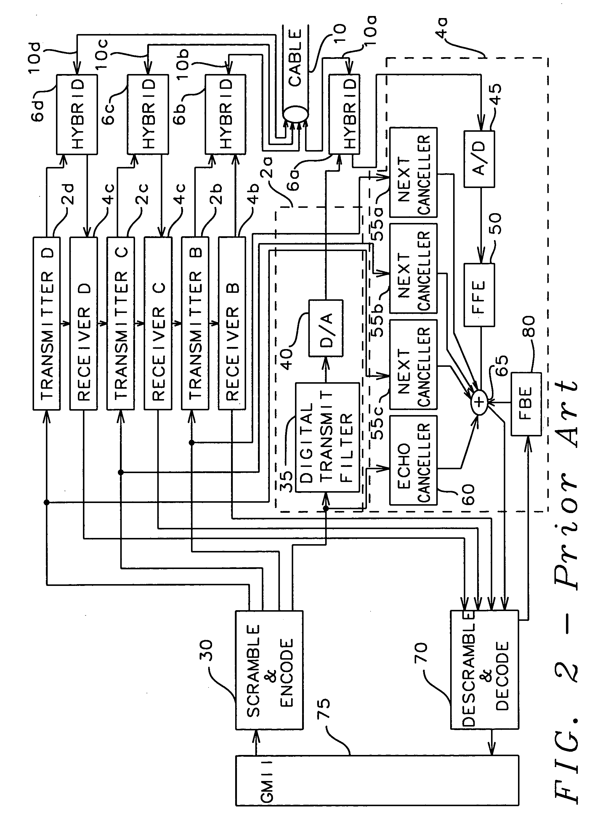
[0075]Since the transmit signals b(k) 120 and the received signals X(k+1) 115 are digitized samples of the signals transmitted and received on the communication medium (cable 10 of FIG. 2), the multiplication can be performed with shift registers. Refer now to FIG. 6 for a discussion of a correlator 100 of the near-end echo / near-end crosstalk canceller of this invention.

[0076]The digital form of the transmitted symbol b(k) is the input to each of the first unit delay elements 305a, 305b, 305c, . . . , 305d to form the delayed transmitted symbols 340a, 340b, 340c, . . . , 340d. The sampled digitized received signal 115 and the delayed transmitted signals 340a, 340b, 340c, . . . , 340d are the inputs to the first shifters 300a, 300b, 300c, . . . , 300d. The first shifters 300a, 300b, 300c, . . . , 300d shift the sampled digitized received signal 115 according to the values of the delayed transmitted signals 340a, 340b, 340c, . . . , 340d to form the output products 345a, 345b, 345c, ....


PUM


Abstract

A communication transmitting and receiving system in which the effects of near-end echo and near-end crosstalk signal from the communication medium are mitigated by adaptively reproducing the near-end echo and near-end crosstalk signal, which is then subtracted from the received signal. Filter coefficients for a Finite Impulse Response filter are adaptively generated to reproduce the near-end echo and near-end crosstalk. The filter coefficients are regenerated for the Finite Impulse Response filter in an adaptive correlator at the arrival of each received signal and whereby each new filter coefficient is a weighted sum of a previous coefficient and one received signal multiplied by a time delayed version of one transmitted signal.

Description

BACKGROUND OF THE INVENTION[0001]1. Field of the Invention[0002]The present invention relates to apparatus and methods for communication of signals in a communication medium. More particularly, this invention relates to apparatus and methods to cancel echo interference and near-end crosstalk interference in a received signal from a transmitter attached to the communication system and from transmitters attached to other communication media in close proximity to the communication media.[0003]2. Description of the Related Art[0004]The gigabit Ethernet (1000 BASE-T) as defined by the IEEE standard 802.3ab is well known in the art. The structure capabilities and design consideration are described in:[0005]“Gigabit Ethernet Over 4-Pair 100 OHM Category 5 Cabling,” Gigabit Ethernet Alliance, Cupertino, Calif., 1999,[0006]“Gigabit Ethernet 1000 Base-T,” 1000 BASE-T Tutorial Series, Interoperability Laboratory Gigabit Ethernet Consortium, University of New Hampshire, Durham, N.H., 1998,[0007...

Claims


Application Information

Patent Timeline
Patent Type & Authority Patents(United States)
IPC IPC(8): H04M9/08H04B3/23H04B3/32
CPCH04B3/23H04B3/32H04B3/238
Inventor KIM, BEOMSUP
Owner MARVELL ASIA PTE LTD
Why Eureka
Try Eureka