
System and method for exact compensation of fundamental phasors

Inactive Publication Date: 2005-08-23
SCHWEITZER ENGINEERING LABORATORIES
View PDF4 Cites 51 Cited by
  • Summary
  • Abstract
  • Description
  • Claims
  • Application Information

AI Technical Summary

Benefits of technology

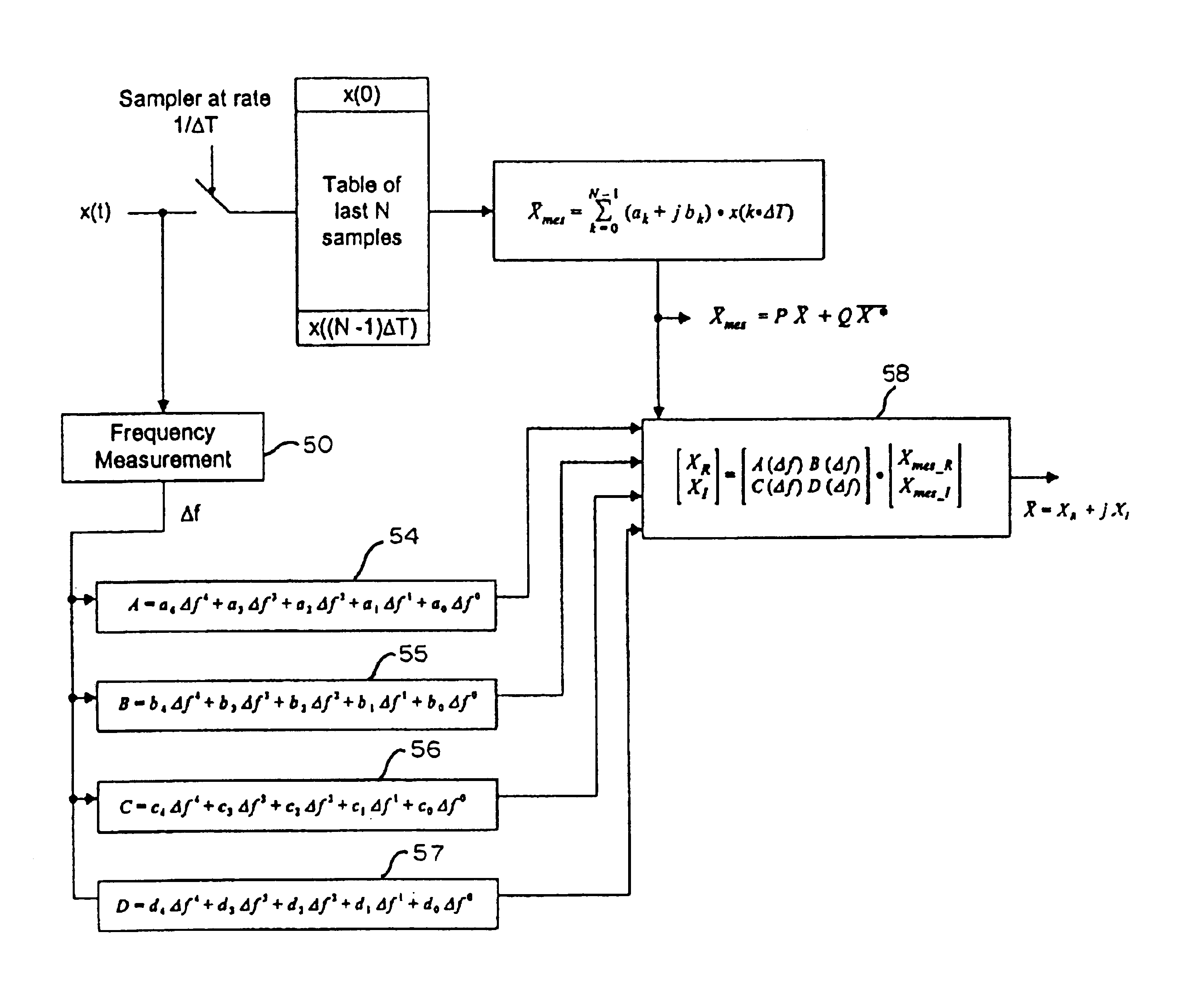
[0007]Accordingly, the present invention is a system and corresponding method for determining an accurate fundamental phasor for a signal waveform from a system, such as a power signal waveform from a power system, where there is a difference between a rated frequency of such waveform for said system and an actual frequency of the waveform at a given point in time, comprising: a circuit for determining a measured phasor, including both real and imaginary parts, representing the signal waveform, without adjusting for frequency of the waveform, wher

Problems solved by technology

However, when the actual power system frequency is different than the rated frequency, the phasor (produced by the two filters) will have errors, both in magnitude and in phase angle; these errors become larger as the actual power signal frequency deviates further from the rated frequency.
Errors in the phasors are undesirable, as they can result in erroneous / poor performance of the protective relay.
However, the Premerlani technique, while providing some correction for phasor errors due to frequency difference, still results in phasors which include some error.
The amount of the error increases as the frequency difference increases.
It cannot be used for other FIR filters, such as Cosine filters.

Method used


Image

  • System and method for exact compensation of fundamental phasors
  • System and method for exact compensation of fundamental phasors
  • System and method for exact compensation of fundamental phasors

Examples


Embodiment Construction

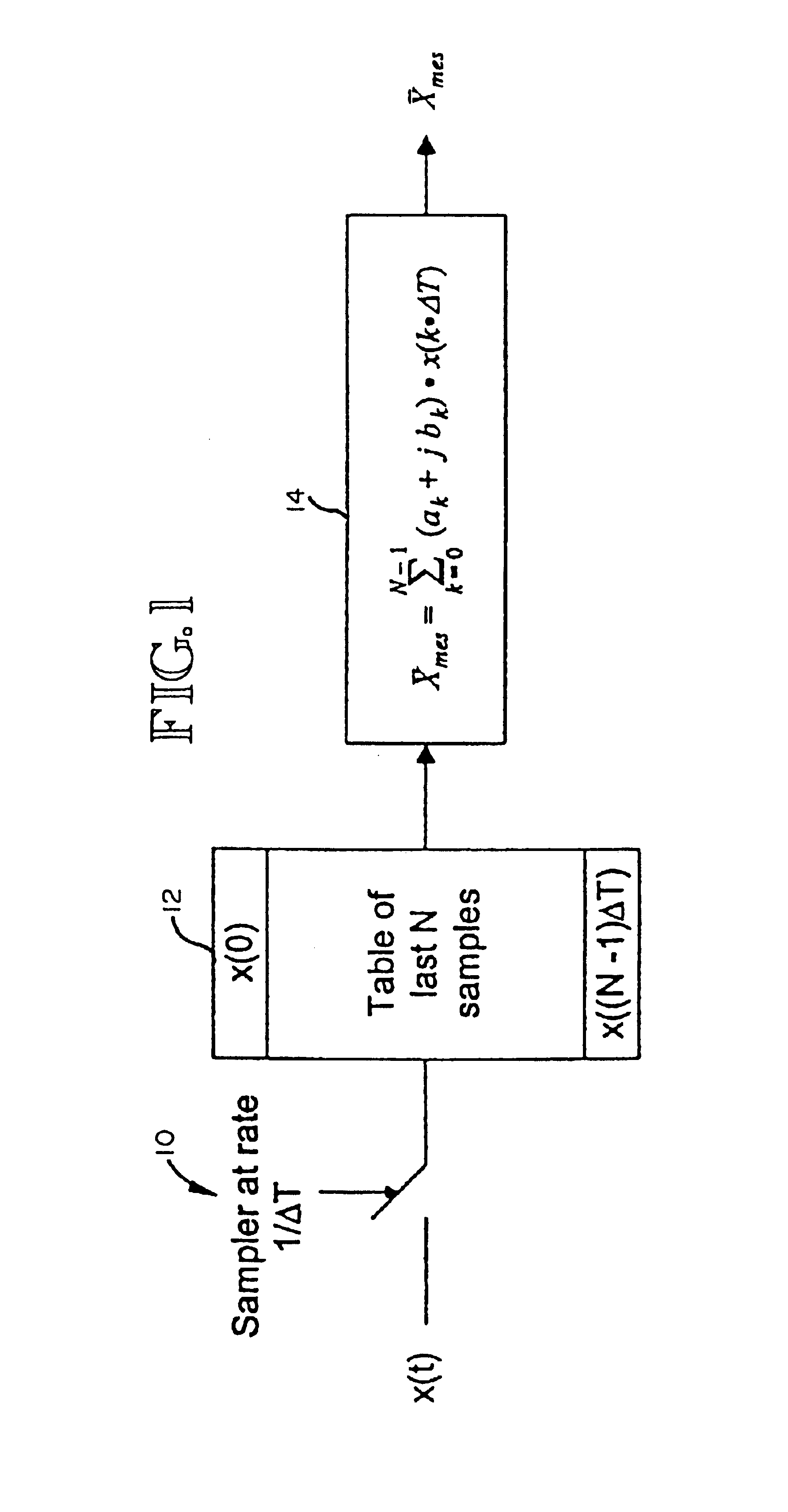
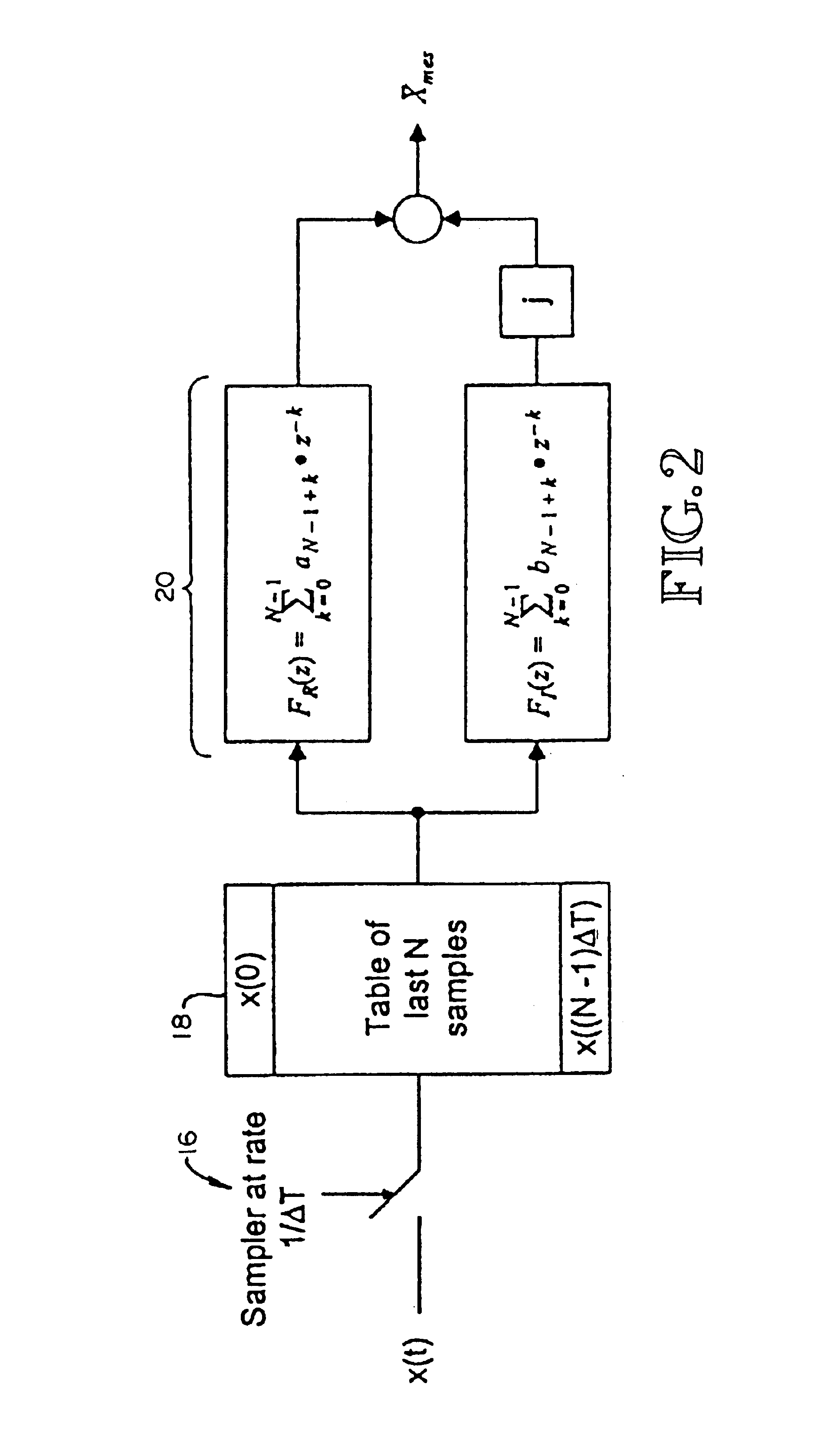
[0014]As discussed briefly above, a pair of orthogonal filters, generally digital finite response (FIR) filters are used to produce the fundamental component phasors representing the voltage and current waveforms of a power system. These phasors are then used by digital protective relays to ascertain power system fault conditions and, when necessary, provide a tripping action. An FIR filter is a digital filter that has an impulse response which is zero outside some finite time interval. Digital filters which utilize this technique include Fourier and Cosine filters. The individual coefficients of the FIR filters are typically selected such that the gain of each filter is unity (1) at the rated frequency of the power system and such that the phase angle between the two outputs of the orthogonal filters is 90° at the rated frequency.

[0015]The system and method of the present invention is directed toward compensating the calculated phasors when the actual frequency of the power system ...


PUM


Abstract

A measured phasor representing a sinusoidal power signal waveform is produced by orthogonal FIR filters, one of which produces the real part of the phasor and the other of which produces the imaginary part. The frequency difference between the rated frequency of the signal waveform in the power system and the actual frequency of the waveform at any selected point in time is determined and the elements (A, B, C, D) of a compensation matrix is determined. The compensation matrix is then used to perform a linear transformation to produce an exact phasor for the waveform.

Description

TECHNICAL FIELD[0001]This invention relates generally to the computation of phasors corresponding to voltage and current waveforms in an electric power system, which are used for instance as inputs to digital protective relays for the power system, and more specifically concerns a system and method for compensating such computated phasors when the actual power system signal frequency is different than its rated frequency, which would otherwise result in errors in the phasors.BACKGROUND OF THE INVENTION[0002]In microprocessor-based protective relays, such as used for protection of electric power systems, a pair of numerical filters is typically used to compute the complex numbers which represent the fundamental component phasors for the power system voltage and current waveforms. The phasors are used by the protective relay to carry out its monitoring and protection functions for the power system. The numerical filters are designed so that their output waveforms are orthogonal, which...

Claims


Application Information

Patent Timeline
IPC IPC(8): H02H1/00G01R21/06
CPCG01R21/06H02H1/0092
Inventor BENMOUYAL, GABRIEL
Owner SCHWEITZER ENGINEERING LABORATORIES
Learn More