
Weather strip having variable length holding lip

a technology of holding lip and weather strip, which is applied in the field of weather strips, can solve the problems of reducing the efficiency of attaching the weather strip to the vehicle body, changing the length, and the control of the length of the holding lip may become complicated, so as to reduce the load or stress, the length of the holding lip, and the effect of large elastic for

Inactive Publication Date: 2005-08-30
TOYODA GOSEI CO LTD
View PDF21 Cites 23 Cited by
  • Summary
  • Abstract
  • Description
  • Claims
  • Application Information

AI Technical Summary

Benefits of technology

[0011]It is one object of the invention to provide a weather strip that can be mounted on the vehicle body with improved reliability or stability, while preventing deterioration in the productivity and the efficiency with which the weather strip is mounted on the vehicle body. It is another object of the invention to provide a method of manufacturing such a weather strip. It is a further object of the invention to provide a weather strip and a method of manufacturing the same, which do not suffer from deterioration in the efficiency in mounting the weather strip on the vehicle body even when a certain degree of variations in the longitudinal position of the weather strip with respect to the vehicle body occur during production and mounting of the weather strip on the vehicle body. It is still another object of the invention to provide a weather strip, a method of manufacturing the weather strip, and a mounting structure of the weather strip on the vehicle body, which are free from a conventional problem(s) at the time of bonding or joining of the end portions of the weather strip, and which do not suffer from a reduction in the production efficiency when a plurality of weather strips are successively produced.
[0013]According to the method as described above, the trim body having a U-shaped cross-section is held by the flange provided at the periphery of the door opening of the vehicle, and the hollow seal portion that protrudes from the trim body is pressed against the periphery of the door upon closing of the door, so that a seal is provided between the vehicle body and the door. Also, the weather strip is kept attached to the flange by means of a holding lip that extends from the inside surface of the trim body toward the inside of the trim body. In manufacturing the weather strip constructed as described above, the weather strip is formed by extrusion molding, during which the length of the holding lip changes in a stepped manner in accordance with the thickness of the flange. Thus, the length of the holding lip is reduced in a portion of the weather strip corresponding to a large-thickness portion of the flange, thereby preventing an otherwise possible increase in a load required for inserting the flange into the trim body of the weather strip. On the other hand, the length of the holding lip is increased in a portion of the weather strip corresponding to a small-thickness portion of the flange, thus assuring a sufficiently large elastic force applied from the holding lip to the flange, and thereby preventing the weather strip from being detached from the flange. Furthermore, the length of the holding lip is not continuously changed, but changed in a stepped manner. Therefore, complicated control will not be required for changing the length of the holding lip, and an otherwise possible increase in the cost can be avoided. Moreover, even in the case where the thickness of the flange varies frequently, the length of the holding lip can be changed without substantial delay, whereby a desired lip length can be achieved. In addition, since it is unnecessary to perform accurate control for continuously changing the length of the holding lip, the extrusion speed can be increased, assuring an improved production efficiency. Even in the case where some variations arise in the longitudinal position of the weather strip relative to the flange during production and mounting thereof, such variations are likely to be absorbed, thus avoiding an otherwise possible increase in the insertion load and reducing a possibility of detachment of the weather strip from the vehicle body.
[0016]In the embodiment as described above, the length of the holding lip corresponding to at least the large-thickness section of the flange is made smaller than the length of the holding lip corresponding to the small-thickness section of the flange. Thus, in the large-thickness section of the flange, in particular, a stress (i.e., the insertion load) is less likely to increase upon fitting of the weather strip on the flange since the length of the holding lip is reduced. Furthermore, each section of the weather strip in which the holding lip has a reduced length is made longer by a predetermined length than the large-thickness section of the flange. Thus, even in the case where some variations arise in the longitudinal position of the weather strip relative to the flange during production and mounting thereof, the insertion load is prevented from increasing due to the presence of a long holding lip in the large-thickness section of the flange. Accordingly, the weather strip can be mounted with improved efficiency.
[0018]In the embodiment as described above, the length of the holding lip is changed along the longitudinal direction of the weather strip in accordance with the thickness of the flange. Thus, the holding lip is shortened in a portion of the weather strip corresponding to a large-thickness portion of the flange, and therefore the flange can be inserted in the trim body of the weather strip with a reduced load or stress. On the other hand, the length of the holding lip is increased in a portion of the weather strip corresponding to a small-thickness portion of the flange, thus assuring a sufficiently large elastic force applied from the holding lip to the flange, and thereby preventing the weather strip from being detached from the flange. Here, the holding lip includes longitudinally opposite end portions having substantially the same length. If the weather strip is formed into an annular shape, for example, the front and rear end faces of the weather strip can be easily and accurately joined to each other. Alternatively, the front and rear end portions of the weather strip are favorably connected to each other using a metal mold molding, without requiring the mold to have a complicated shape or construction. If a plurality of weather strips are to be continuously formed by extrusion molding, the weather strips can be successively produced without loss or waste, while preventing deterioration in the yield and the production efficiency.

Problems solved by technology

In this case, if the size (length) of each holding lip is constant over the entire circumference of the weather strip, a load (which will be called “insertion load”) required for inserting the flange into the trim body becomes large in a portion where the thickness of the flange is large, resulting in a reduced efficiency in attaching the weather strip to the vehicle body.
However, in the case where the thickness of the flange frequently changes, it is necessary to frequently change the length of each holding lip as well.
Thus, the control of the length of the holding lips may become complicated, which may result in an increase in the cost.
In addition, a desired projection length of the holding lip cannot be achieved if the length of the holding lip is changed with delay in relation to the thickness of the flange during extrusion molding.
For avoiding this, therefore, the extrusion speed needs to be reduced to some extent, which, in turn, may result in a deterioration in the productivity or production efficiency.
If such variations occur, the significance of precisely changing the length of the holding lip in accordance with the thickness of the flange may be lost.
In this case, the insertion load may be undesirably large.
Besides, such variations in the longitudinal position of the weather strip during production and mounting on the flange may cause the following problem.
Furthermore, if the length of the holding lip is changed in accordance with the thickness of the flange as described above, the following problem may occur.
However, if the opposite end faces have different shapes (in this example, if the holding lip has different projection lengths at the end faces), the end faces may not be appropriately bonded to each other, or the structure of the mold used for connecting the opposite end portions of the weather strip may be undesirably complicated, causing a difficulty in connecting the end portions by using the mold.

Method used


Image

  • Weather strip having variable length holding lip
  • Weather strip having variable length holding lip
  • Weather strip having variable length holding lip

Examples


first embodiment

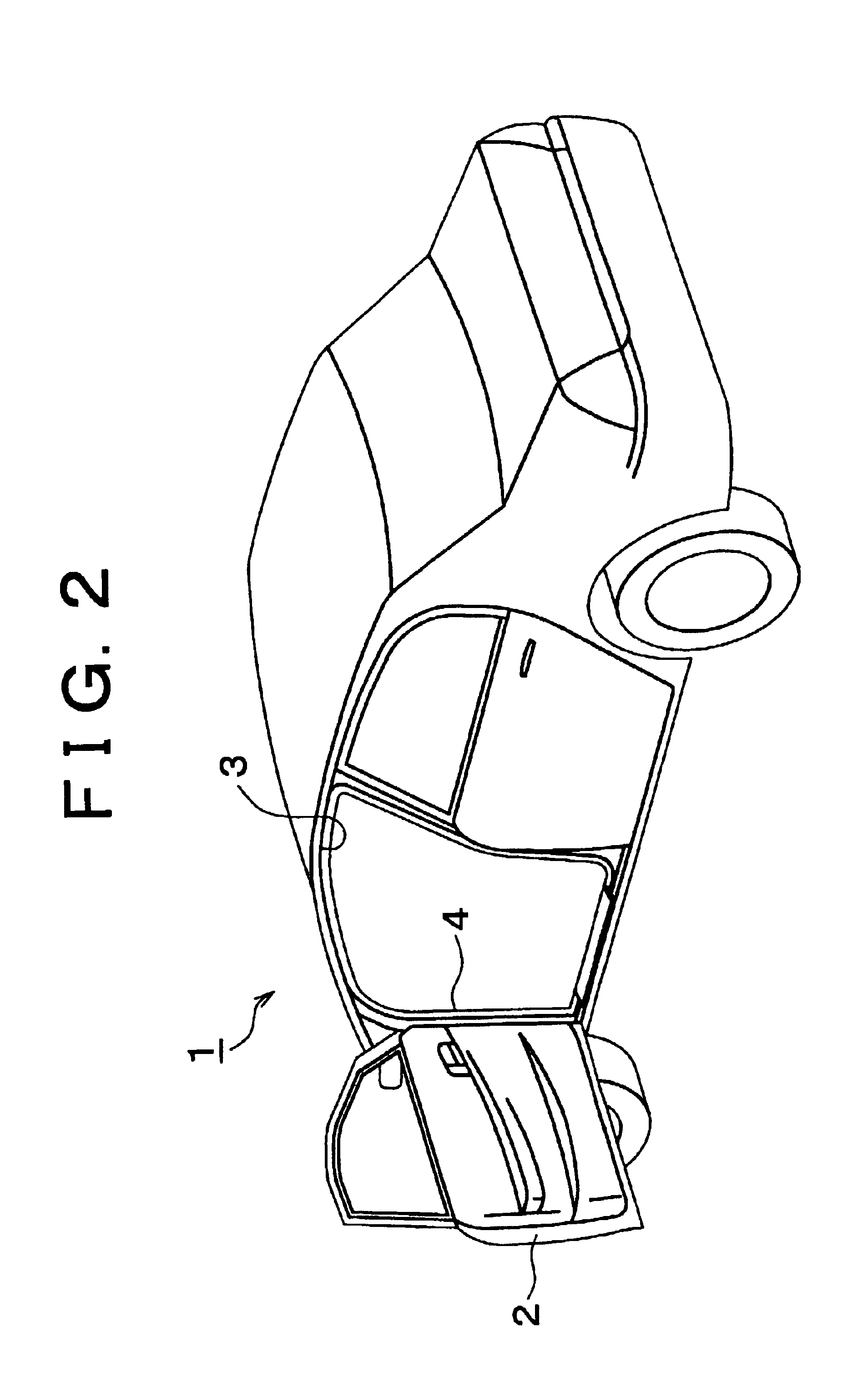
[0038]Hereinafter, the invention will be described with reference to the attached figures. As shown in FIG. 2, a weather strip 4 is provided on a periphery of a door opening 3 that faces α door 2 located on one side of a vehicle 1. The weather strip 4 of the embodiment is attached to the entire periphery of the door opening 3 except for its bottom portion, and is entirely formed by extrusion molding.

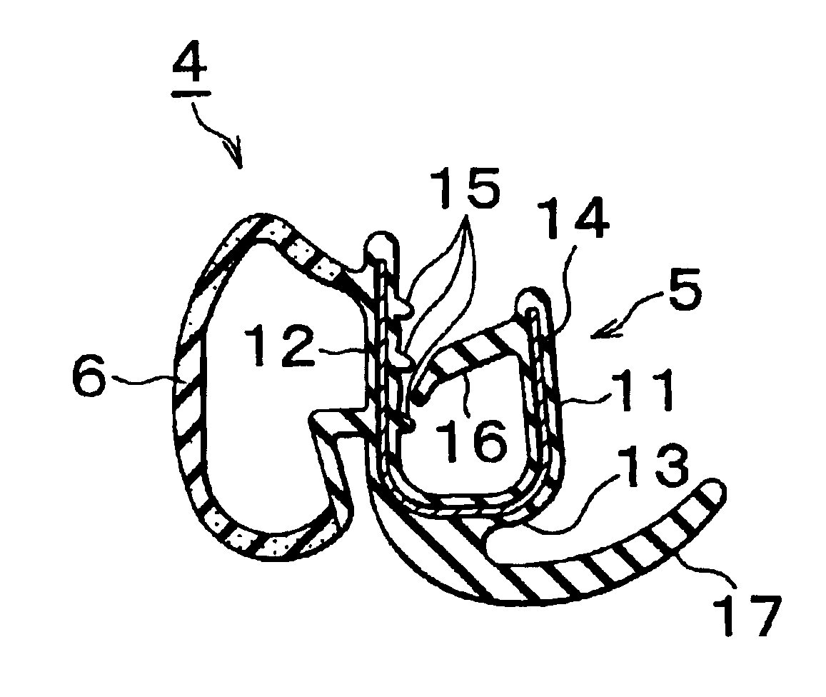
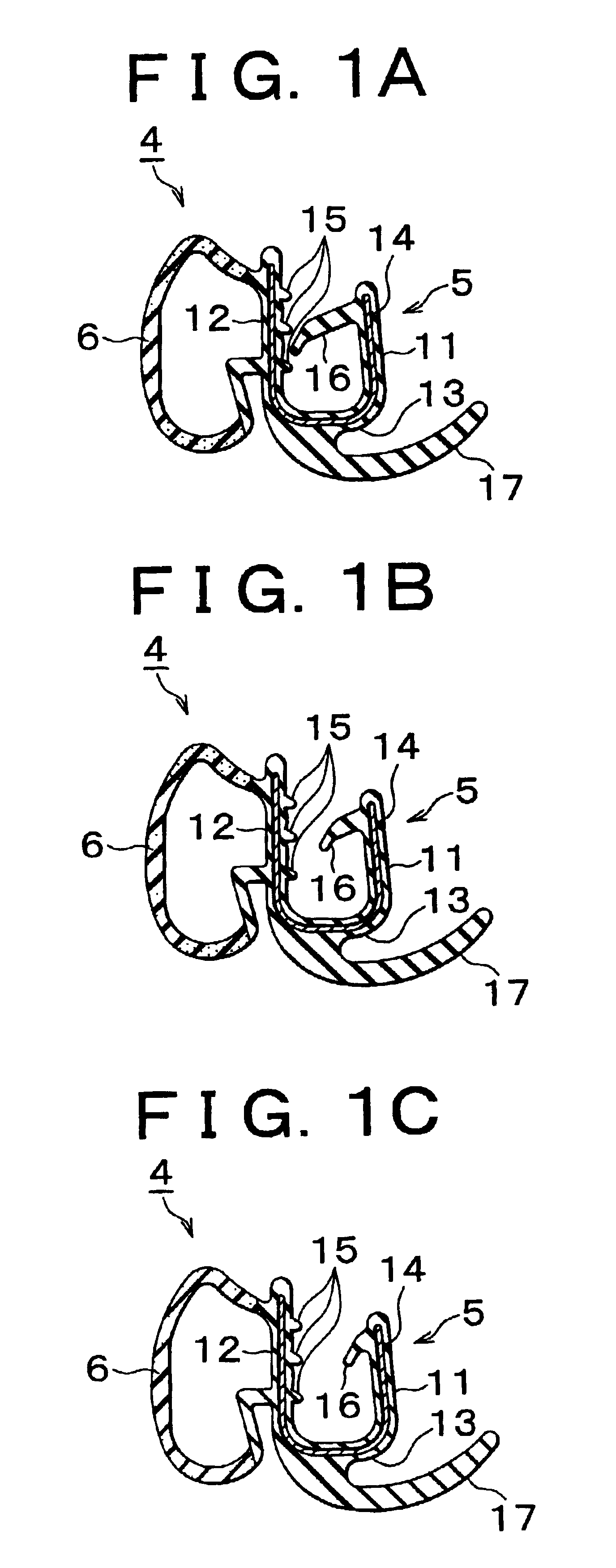
[0039]As shown in FIGS. 1A to 1C and FIGS. 3A to 3C, the weather strip 4 includes a trim body 5 and a seal portion 6. The trim body 5 includes an inner sidewall 11 facing the inside of the vehicle, an outer sidewall 12 facing the outside of the vehicle, and a connecting portion 13 connecting the sidewalls 11, 12. The connecting portion 13 has a substantially curved shape in section and thus the trim body 5 as a whole has a substantially U-shaped cross section. The trim body 5 is formed of EPDM (ethylene-propylene-diene terpolymer) solid rubber and includes a metal insert 14 embedded ther...

third embodiment

[0073]Hereinafter, the invention will be described with reference to FIG. 8 and FIG. 9. As shown in FIG. 8, the weather strip 4 is provided on the periphery of the door opening 3 that faces the door 2 disposed on one side of the vehicle 1. The weather strip 4 according to this embodiment is attached to the entire periphery of the door opening 3, and is entirely formed by extrusion molding. The weather strip 4 is obtained as one of a plurality of whether strips formed by extrusion molding. As shown in FIG. 9, the opposite end faces α and β of the weather strip 4 are joined to each other. A portion of the weather strip 4 in which the end faces α and β are joined together is located at the lower, front side of the door opening 3 (i.e., the lower, left side in FIG. 3).

[0074]As in the first embodiment as shown in FIGS. 1A to 1C and FIGS. 3A to 3C, the weather strip 4 according to the third embodiment includes the trim body 5 and the seal member 6. A plurality of the holding lips 15 are f...

fourth embodiment

[0090](h) While the length of the variable holding lip 16 is changed among three lengths throughout the entire circumference of the weather strip 51 in the fourth embodiment, the length of the variable holding lip 16 may be continuously and gradually changed in one or more portion(s) of the weatherstrip 51.

[0091](i) While the weather strip 51 is not provided in the predetermined bottom portion of the door opening 3 in the fourth embodiment, the weather strip 51 may be provided in the predetermined bottom portion of the door opening 3. Namely, even if the scuff plate 52 is provided as in the fourth embodiment, the weather strip 51 may be attached to the entire circumference of the door opening 3.

[0092](j) The engaging member(s) 55 as used in the fourth embodiment may be eliminated, and the scuff plate 52 may be directly fitted onto the flange 23.

[0093](k) While the scuff plate 52 covers the entire weather strip 51 having the trim body 5 and the seal member 6 in the fourth embodiment,...


PUM


Abstract

A weather strip includes a trim body having a generally U-shaped cross section, a hollow seal portion that protrudes from an outside surface of the trim body, and a holding lip formed on the trim body so as to extend from an inside surface of the trim body toward the inside of the trim body. The weather strip is mounted on the vehicle body such that the trim body is held by a flange provided at a periphery of a door opening of a motor vehicle. The weather strip is formed by extrusion molding such that the length of the holding lip is changed in a stepped manner in accordance with the thickness of the flange.

Description

INCORPORATION BY REFERENCE[0001]The disclosures of Japanese Patent Applications No. 2001-212995 filed on Jul. 13, 2001, No. 2001-212996 filed on Jul. 13, 2001, No. 2001-215192 filed on Jul. 16, 2001 and No. 2001-228317 filed on Jul. 27, 2001, each including the specification, drawings and abstract, are incorporated herein by reference in their entirety.BACKGROUND OF THE INVENTION[0002]1. Field of the Invention[0003]The invention relates to a weather strip provided on a periphery of a door opening of a motor vehicle, and also relates to a method of manufacturing the weather strip.[0004]2. Description of Related Art[0005]Generally, a weather strip, or the like, is provided on a periphery of a door opening of a motor vehicle, such as an automobile. The weather strip includes a trim body having a substantially U-shaped cross section, and a seal portion that has a hollow shape and projects from the trim body. The trim body is fitted onto a flange provided at the periphery of the door ope...

Claims


Application Information

Patent Timeline
Patent Type & Authority Patents(United States)
IPC IPC(8): B60J10/00B60J10/08
CPCB60J10/0011B60J10/002B60J10/0031B60J10/0051B60J10/0062B60J10/0065B60J10/0068B60J10/08B60J10/18B60J10/22B60J10/24B60J10/265B60J10/30B60J10/32B60J10/33B60J10/80
Inventor KOGISO, HARUMIMINE, KIMINORIOHASHI, MASAKISATO, TAKAAKINISHIKAWA, TOMOFUMINOZAKI, MASAHIRONAHARA, TOSHIHIRO
Owner TOYODA GOSEI CO LTD
Learn More