Method for producing flexographic printing plates by means of laser engraving

a technology of laser engraving and printing plate, applied in the field of process for the production of flexographic printing plate, to achieve the effect of high resolution

Inactive Publication Date: 2005-08-30
XSYS PRINT SOLUTIONS DEUT GMBH
View PDF11 Cites 56 Cited by
  • Summary
  • Abstract
  • Description
  • Claims
  • Application Information

AI Technical Summary

Benefits of technology

[0013]It is an object of the present invention to provide an improved process for the production of flexographic printing plates by laser engraving which enables the occurrence of melt edges to be avoided and significantly

Problems solved by technology

It was also particularly surprising and unexpected to the person skilled in the art t

Method used


Image

  • Method for producing flexographic printing plates by means of laser engraving
  • Method for producing flexographic printing plates by means of laser engraving
  • Method for producing flexographic printing plates by means of laser engraving

Examples


example 1

[0059]The procedure was as in the comparative example, but 1% by weight (based on the sum of all components of the layer) of a finely divided pyrogenic silicon dioxide having a specific surface area of 160 m2 / g and a mean primary particle size of from 10 to 20 nm (AEROSIL® R 8200, Degussa) was added as filler during production of the flexographic printing element.

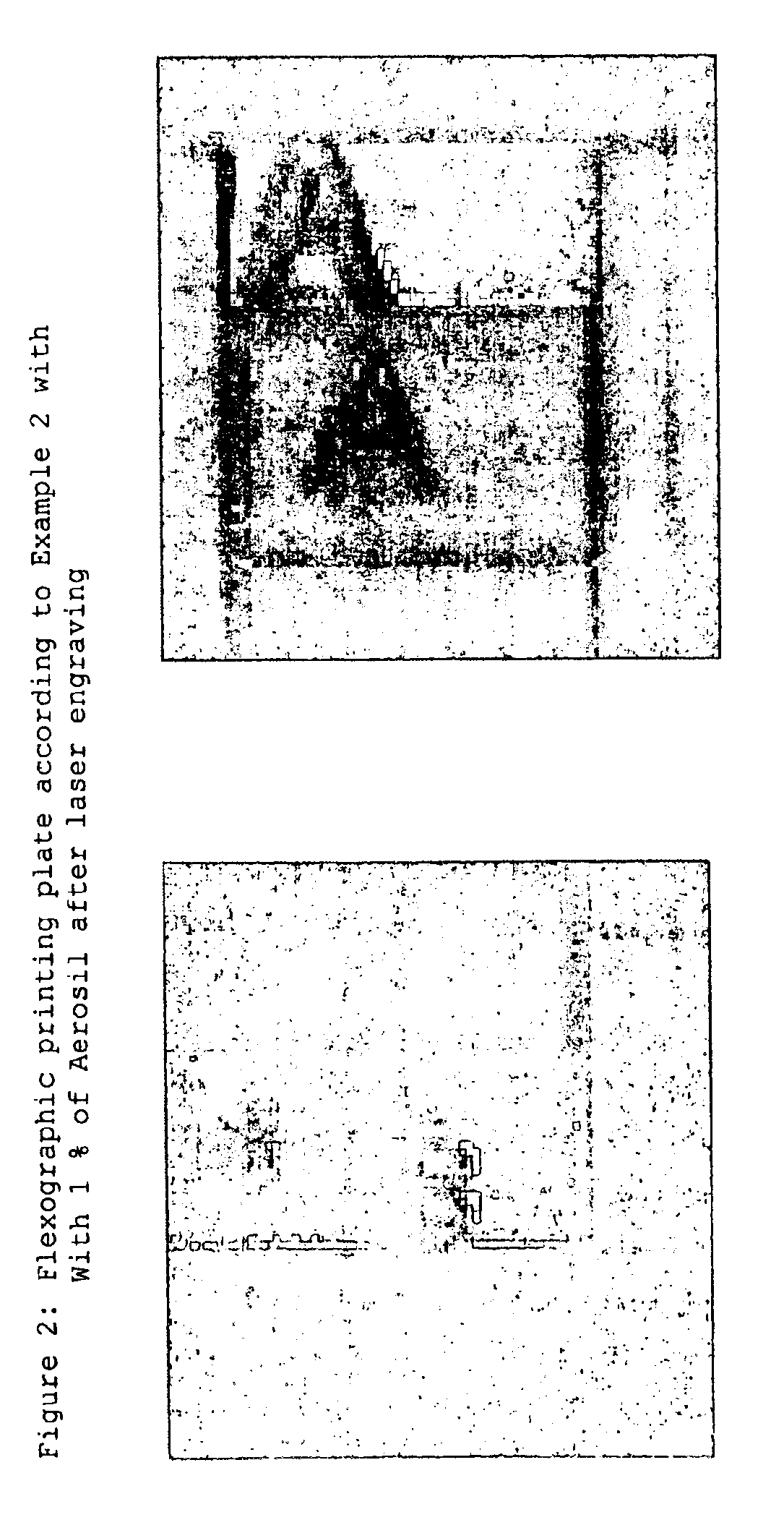
[0060]The experimental results are shown in Table 1. FIG. 2 shows a photomicrograph of the resultant test motif.

examples 2-3

[0061]The procedure was as in the comparative example, but the amounts of silicon dioxide stated in Table 1 were added as filler during production of the flexographic printing element. The experimental results are shown in Table 1.

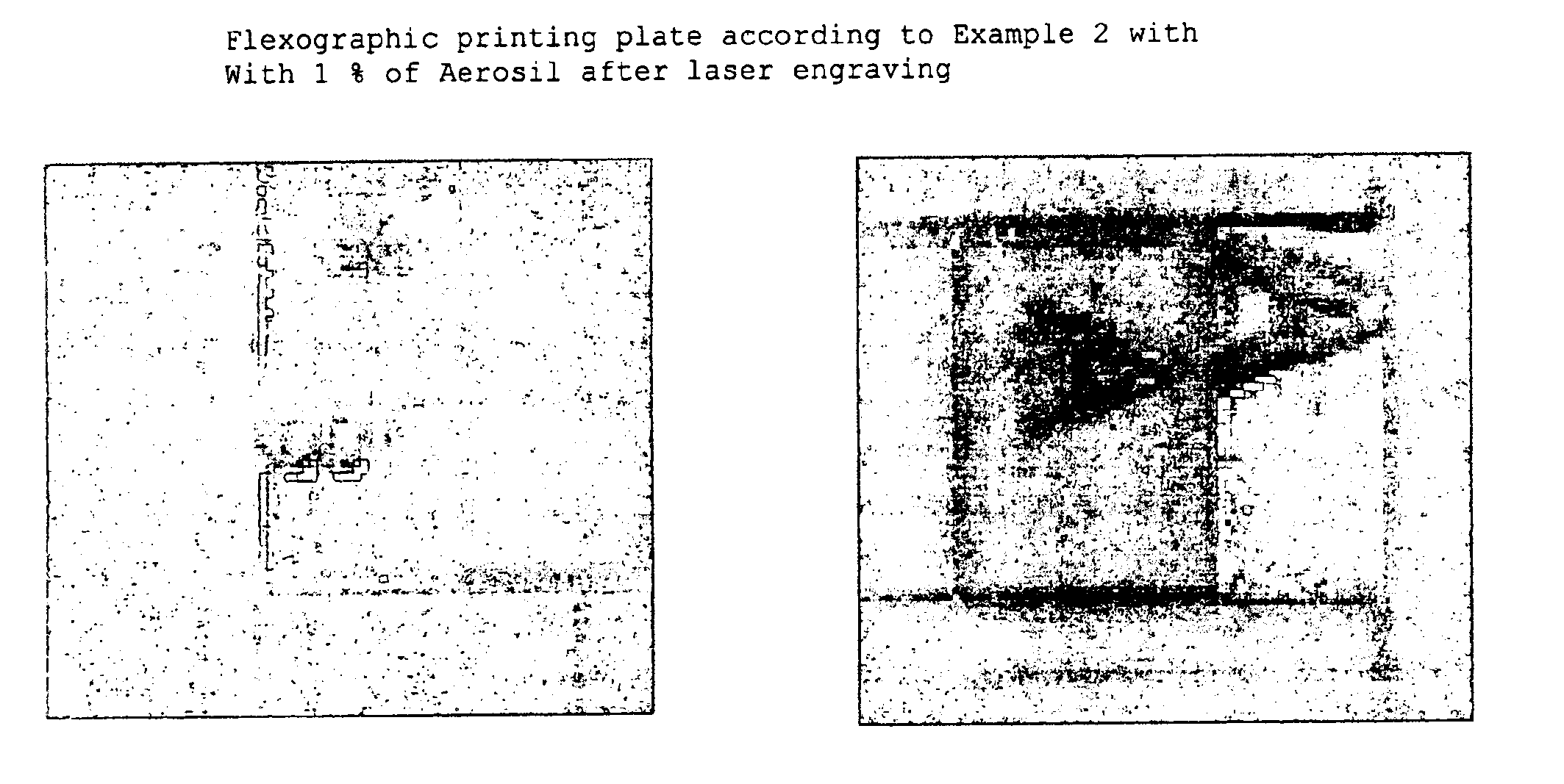
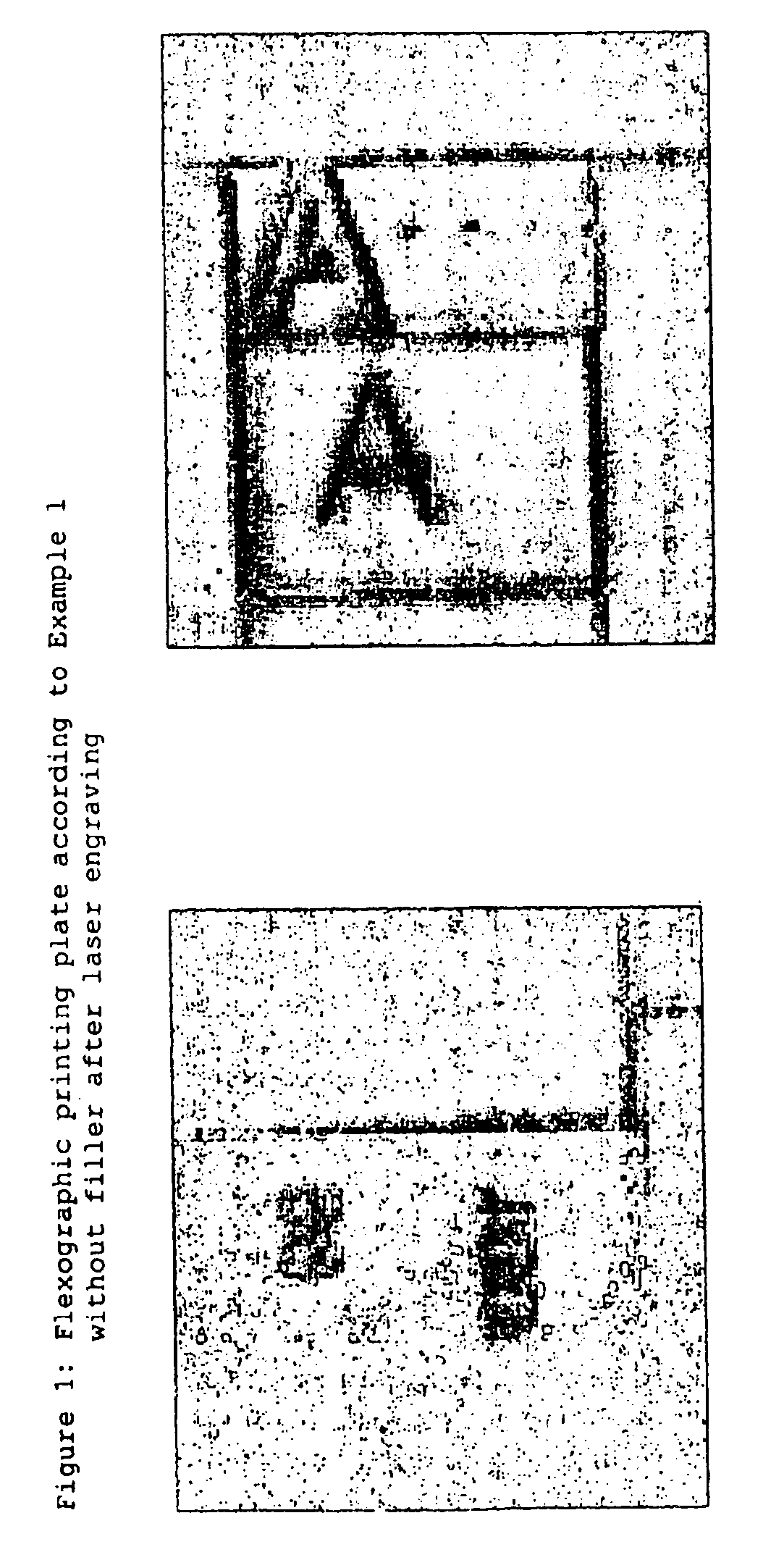
[0062]The engraving results obtained show that the addition according to the invention of only 1% of filler already resulted in a drastic improvement in resolution. While in the case of the plate without filler lines at a separation of 20 μm can no longer be resolved at all and instead coincide to form a single line, the two lines can be resolved in the presence of 1% of SiO2.

[0063]The figures show that the edges of the positive elements shown are significantly sharper if the filler is present. Without filler, dark melt droplets are evident at the edges, which are not present in the case of the plates filled in accordance with the invention.

[0064]The negative element can also be seen significantly better in the case of the filled plate.

[0065]

TABLE 1Results...


PUM

PropertyMeasurementUnit
Percent by massaaaaaaaaaa
Particle sizeaaaaaaaaaa

Abstract

The invention relates to a method for producing flexographic printing forms by engraving a printing relief on a flexographic printing element that can be laser engraved, said element having a photochemically cross-linked relief layer. The relief layer is transparent and comprises oxidic, siliceous or zeolitic solid matter with a particle size between 1 and 400 nm in a quantity of between 0.1 and 8 wt. % in relation to the quantity of all components in the relief layer.

Description

BACKGROUND OF THE INVENTION[0001]The present invention relates to a process for the production of flexographic printing plates by engraving a printing relief into a laser-engravable flexographic printing element which has a photochemically crosslinked relief layer, where the relief layer is transparent and comprises an oxide, silicate or zeolite solid having a particle size of from 1 to 400 nm in an amount of from 0.1 to 8% by weight, based on the amount of all components of the relief layer.[0002]In the technique of laser direct engraving for the production of flexographic printing plates, a relief which is suitable for printing is engraved directly into a relief layer which is suitable for this purpose. Although the engraving of rubber printing cylinders by means of lasers has in principle been known since the end of the 1960s, this technique has, however, only achieved broader commercial interest in recent years with the appearance of improved laser systems. The improvements in t...

Claims


Application Information

Patent Timeline
IPC IPC(8): B41C1/02B41C1/05B41N1/12
CPCB41C1/05
Inventor HILLER, MARGITSCHADEBRODT, JENSKACZUN, JURGENNIEDERSTADT, DIETER
Owner XSYS PRINT SOLUTIONS DEUT GMBH
Why Eureka
Try Eureka