Ventilation system with humidity responsive ventilation controller

a technology of ventilation controller and humidity, which is applied in ventilation systems, heating types, instruments, etc., can solve the problems of mold growth, humid conditions in rooms, condensation or dew on the room's surface, etc., and achieve satisfactory humidity level, prevent, or reduce, the effect of humidity

Inactive Publication Date: 2005-08-30
ACKER PHILLIP F
View PDF11 Cites 82 Cited by
  • Summary
  • Abstract
  • Description
  • Claims
  • Application Information

AI Technical Summary

Benefits of technology

[0010]In accordance with the present invention, a ventilation system is provided that incorporates a ventilation controller constructed to be mounted inside, or in place of, a standard electrical junction box, wherein the ventilation controller activates and deactivates an exhaust fan, as needed, to reduce humidity. The ventilation system incorporates at least one humidity sensor in wired or wireless communication with the ventilation controller. The ventilation controller preferably incorporates an integrated circuit providing logic controls, although it may incorporate a mechanical humidity controller as known in the art. Generally, the ventilation controller is usable to maintain a satisfactory humidity level and to prevent, or reduce, mold growth. Importantly, it acts to prevent condensation and dewing in a fully automated manner.

Problems solved by technology

Rooms, particularly bathrooms, with poor ventilation can be regularly subjected to humid conditions.
Under such conditions, moist air can have difficulty exiting the room, resulting in condensation or dewing on the room's surfaces.
Moisture, in general, can lead to mold growth.
Mold has been known to cause serious illness and extensive property damage.
Typically, rooms subject to high humidity contain ventilation systems that use an exhaust fan to expel the humid air from the room to the atmosphere, but these systems have known deficiencies.
First, most ventilation systems are limited by their dependence on human operators to manually actuate a power switch.
However, people often forget to activate the switch, especially before it is needed.
Therefore, high moisture conditions exist by the time the system is activated, if it ever is.
These ventilation systems are uneconomical because they always activate the fan, even during non-humid conditions.
Besides increased power usage, these systems needlessly expel conditioned air (heated or cooled) from the room.
Other problems include users shutting off the lights before the excess moisture has been fully removed from the room, or they may never turn on the room's lights to begin with.
These systems are also wasteful if they continue to run after the humidity has already been expelled.
On the other hand, timed systems may not run long enough to fully dehumidify the room.
Basically, these ventilation systems are ineffective and wasteful because they are not automated.
They also do not ensure that moisture will be adequately removed from a room.
These settings are often predefined and may not apply to the environmental conditions for various geographical areas.
As a result, it is possible the device will perform poorly because the operating parameters, such as geographical and seasonal changes, were not accounted for.
A drawback to this method is that environmental humidity can fluctuate as the temperature changes each day, causing the ambient humidity to exceed the reference value.
As a result, the fan may fail to operate when it is needed or may operate needlessly.

Method used


Image

  • Ventilation system with humidity responsive ventilation controller
  • Ventilation system with humidity responsive ventilation controller
  • Ventilation system with humidity responsive ventilation controller

Examples


Embodiment Construction

[0023]While the invention is described herein with reference to illustrative embodiments for particular applications, it should be understood that the invention is not limited thereto. Those having ordinary skill in the art and access to the teachings provided herein will recognize additional modifications, applications and embodiments with the scope thereof and additional fields in which the present invention would be of significant utility.

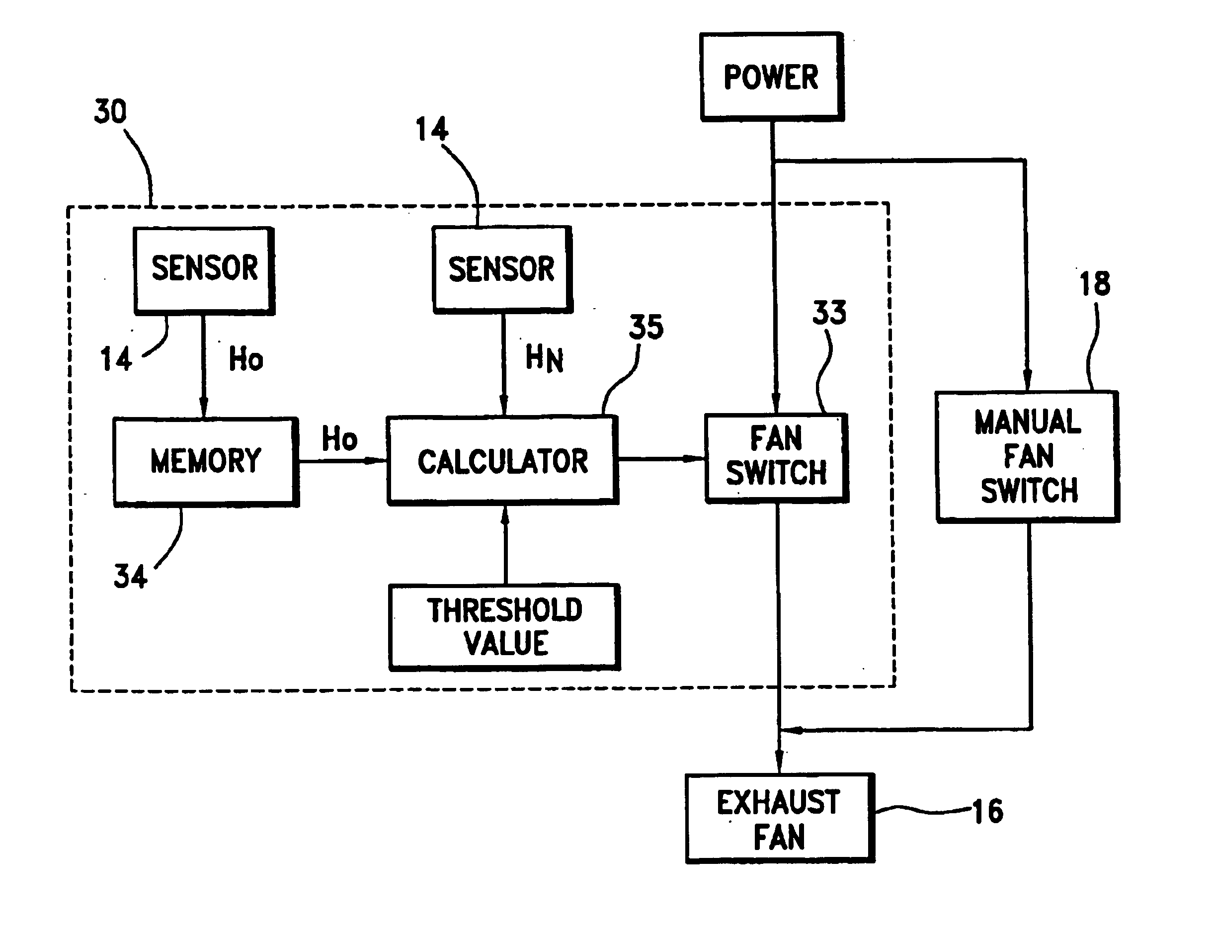
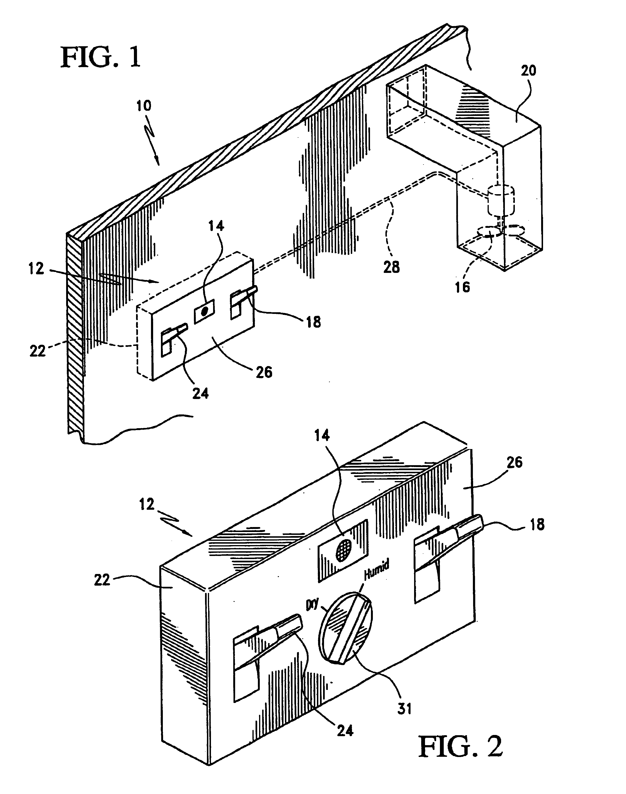
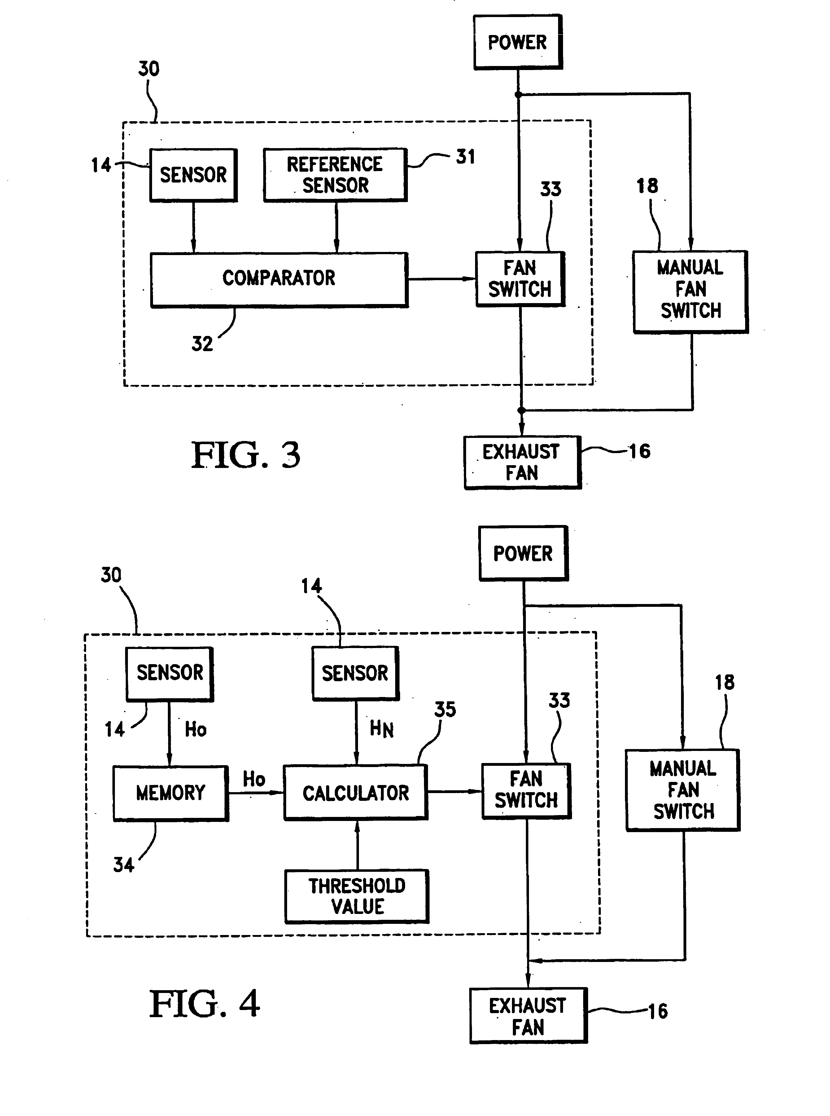
[0024]Referring initially to FIG. 1, there is illustrated generally at 10 a first preferred embodiment of a ventilation system in accordance with the present invention. In this first preferred embodiment, a ventilation controller 12 incorporates a single humidity sensor 14. Ventilation controller 12 is connected to switch on power to an exhaust fan 16 and it may include a manual fan switch 18, which, if included, activates exhaust fan 16 directly, bypassing controller 12. The manual fan switch could operate the fan indefinitely or for a set peri...


PUM


Abstract

A ventilation controller including at least one humidity sensor for controlling the humidity of a room. The ventilation controller incorporates a housing sized and shaped to replace, or be placed in, a standard electrical junction box. Circuitry in the controller receives data from the sensor(s). The controller automatically switches on power to an exhaust fan when either the humidity exceeds a manually set humidity level and/or a rapid increase in humidity is observed. When a plurality of sensors is employed, the humidity level from a first sensor is compared by logic circuitry to the humidity levels detected at a reference sensor(s). When the humidity at the first sensor exceeds the humidity at the reference sensor(s), the ventilation controller switches on power to the exhaust fan.

Description

[0001]This application claims the benefit of U.S. Provisional Application No. 60 / 407,677 filed Sep. 3, 2002, the disclosure of which is hereby incorporated herein by reference.FIELD OF THE INVENTION[0002]The present invention relates generally to a ventilation system with an environmental controller. More particularly, this invention relates to a ventilation controller for reducing or preventing humidity in a room.BACKGROUND OF THE INVENTION[0003]Rooms, particularly bathrooms, with poor ventilation can be regularly subjected to humid conditions. Under such conditions, moist air can have difficulty exiting the room, resulting in condensation or dewing on the room's surfaces. Moisture, in general, can lead to mold growth. Mold has been known to cause serious illness and extensive property damage.[0004]Typically, rooms subject to high humidity contain ventilation systems that use an exhaust fan to expel the humid air from the room to the atmosphere, but these systems have known deficie...

Claims


Application Information

Patent Timeline
Patent Type & Authority Patents(United States)
IPC IPC(8): F24F11/00G05D22/02G05D22/00F24F7/00
CPCF24F11/0001F24F11/0008F24F11/0015G05D22/02F24F11/0079F24F2007/001Y02B30/746F24F11/30F24F2110/20F24F11/77Y02B30/70F24F11/49
Inventor ACKER, JR., PHILLIP F.
Owner ACKER PHILLIP F
Why Eureka
Try Eureka