Hook device

a hook and a technology of hooks, which is applied in the field of hook devices, can solve the problems of high cost and difficulty in assembling or disassembling the hook devices, and achieve the effects of preventing plastic deformation or failure, and simple and handy hook devices

Inactive Publication Date: 2005-08-30
NIFCO INC
View PDF16 Cites 31 Cited by
  • Summary
  • Abstract
  • Description
  • Claims
  • Application Information

AI Technical Summary

Benefits of technology

[0008]With this configuration, when the hook device is assembled with the case member with an angle deviated from a regular rotational range between the store position and the use position in a widely opened state, the elastic member appropriately deforms, so that the hook main portion can be rotated in the regular rotational range. Therefore, the hook main portion can be assembled with the case member with any relative angle to thereby facilitate the assembling work. Also, when the hook device is disassembled, the elastic member can deform to move the engaging portion to a position not to cause interference with the stopping portion by pushing with a finger or the like. Accordingly, the hook main portion can be opened wider than the rotational range regulated by the stopping portion to thereby facilitate the disassembling work.
[0010]According to the third aspect of the invention, in the hook device described above, the elastic member elastically deforms in a direction that the stopping portion is released from the engaging portion when a load is applied to the hook main portion in the direction that the hook main portion opens. With this structure, when a load larger than the load limit is applied, the stopping portion is released from the engaging portion, thereby preventing plastic deformation or failure. In this case, in consideration of the direction of the rotational force applied to the hook main portion due to the load, the stopping portion and engaging portion may have cross sections so that when a load is applied to the hook main portion, the engaging portion is guided to move away from the stopping portion.
[0011]According to the fourth aspect of the invention, in the hook device described above, a spring may be provided for urging the hook main portion in an opening direction. Further, a latch mechanism may be provided for holding the hook main portion at a predetermined store position against the spring urging force. With this structure, the stopping portion regulates the hook main portion at the use position. Also, the latch mechanism holds the hook main portion at the store position, thereby making the hook device simple and handy.

Problems solved by technology

However, in a case that the regular rotational range is set to be narrow according to a layout of the hook device, it is difficult to assemble or disassemble the hook device.
Therefore, a load limit of the hook device is determined by the strength of these portions, and it would result in a high cost to increase the strength.

Method used


Image

  • Hook device
  • Hook device
  • Hook device

Examples


Embodiment Construction

[0019]Hereunder, embodiments of the present invention will be described in detail with reference to the accompanying drawings.

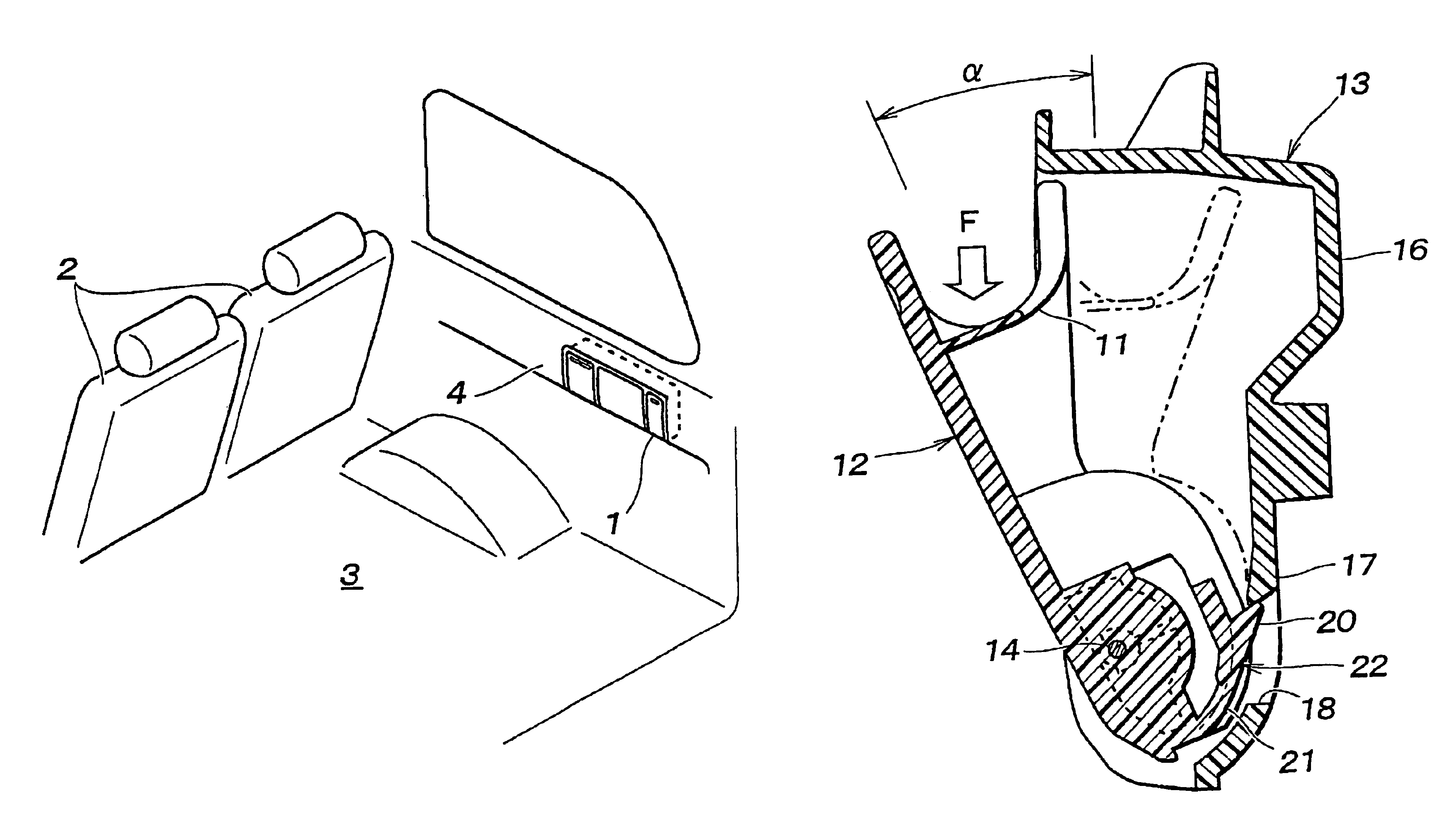
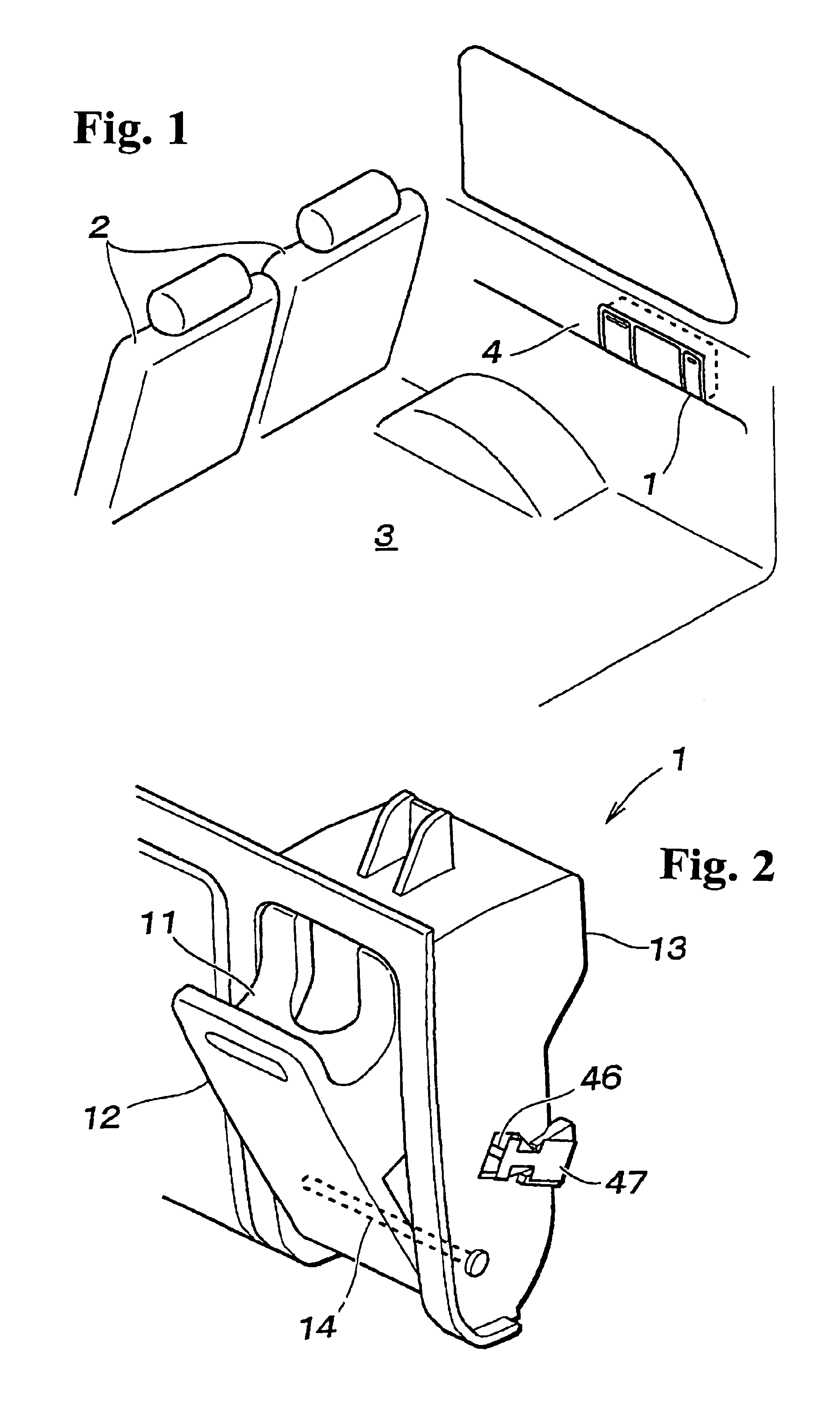
[0020]FIG. 1 is a perspective view showing a compartment in a vehicle where the present hook device is applied. A hook device 1 according to the present invention is provided on a sidewall surface of a rear luggage space 3, and baggage such as a shopping bag is suspended from the hook device 1 to be held thereat. The hook device 1 is installed in an interior member 4 so that a front surface of the hook device 1 is exposed on the interior member 4. Incidentally, the hook device 1 is installed with other accessories such as a power plug.

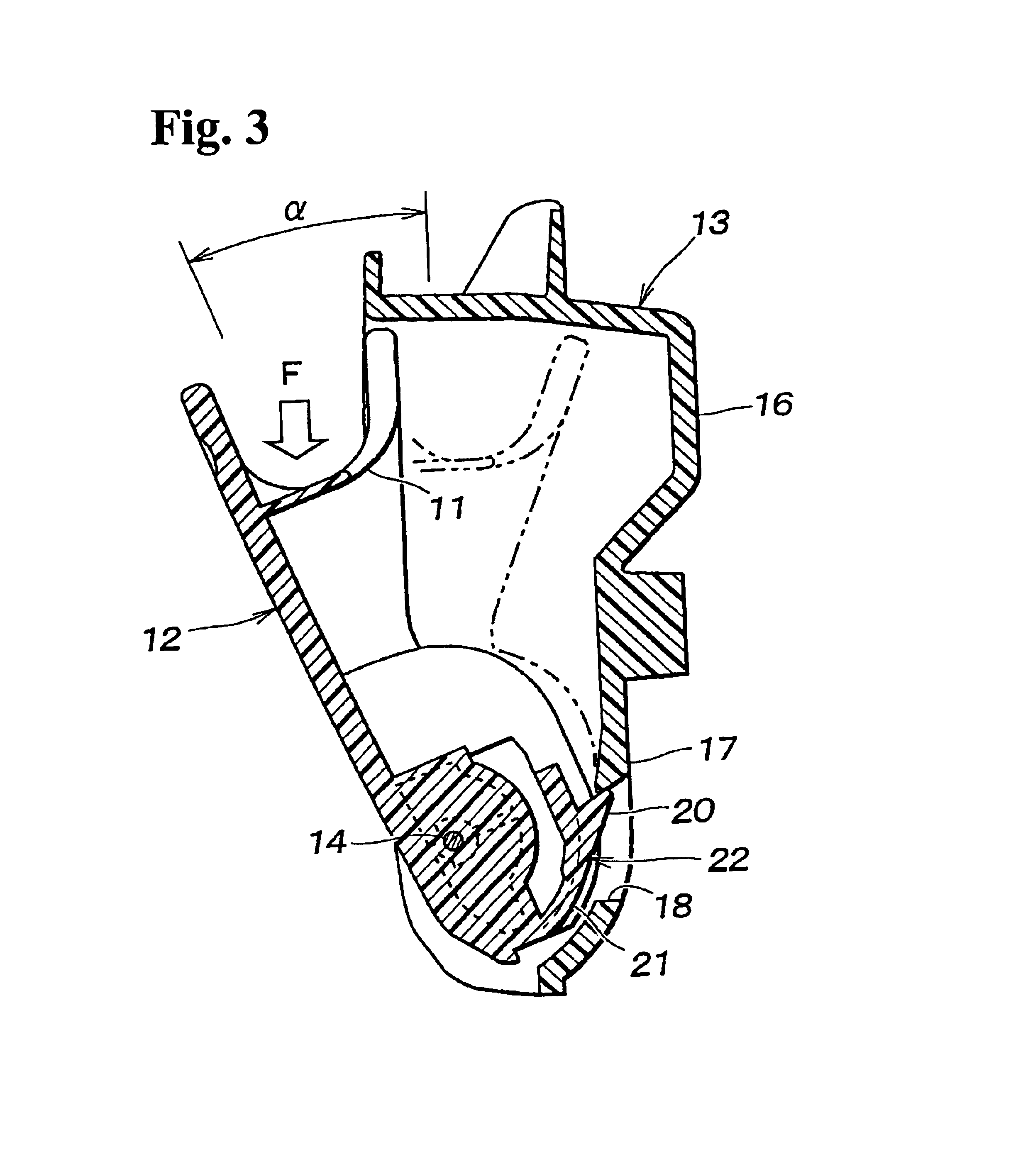
[0021]FIG. 2 is a perspective view showing the hook device according to the present invention. The hook device 1 includes a hook main portion 12 having a hook portion 11 for suspending baggage and a case member 13 for supporting the hook main portion 12 rotatably between a store position and a use position. A support shaft 14 fo...


PUM


Abstract

A hook device includes a case member for supporting a hook main portion to be rotatable between a store position and a use position; a stopping portion attached to the case member for regulating the hook main portion at the use position with a predetermined opening angle; and an engaging portion provided to the hook main portion through an elastic member for engaging the stopping portion. The elastic member elastically deforms in a direction that the stopping portion engages the engaging portion when a load is applied to the hook main portion in a direction that the hook main portion opens.

Description

BACKGROUND OF THE INVENTION AND RELATED ART STATEMENT[0001]The present invention relates to a hook device to be disposed in a compartment of a vehicle or the like for suspending baggage therefrom. More particularly, the present invention relates to a hook device capable of being stored when the hook is not used.[0002]In a hook device disposed in a compartment of a vehicle or the like, it is preferred that the hook device has a retractable structure so that the hook device does not become an obstacle when the hook device is not used. As such a retractable hook device, there has been known a hook device having a structure wherein a case member supports a hook main portion to be rotatable between a store position and a use position as disclosed in Japanese Patent Publication (Kokai) No. 8-282385.[0003]In the retractable hook device described above, a stopping portion is provided to the case member for regulating a rotational range of the hook main portion. When the hook device is assem...

Claims


Application Information

Patent Timeline
Patent Type & Authority Patents(United States)
IPC IPC(8): B60R7/00B60R7/10B60R7/02B60N3/00
CPCB60R7/02B60R7/10Y10S224/927A47G25/0607
Inventor TANAKA, TSUTOMU
Owner NIFCO INC
Why Eureka
Try Eureka