Mechanical broadhead with sliding blades

a technology of sliding blades and broadheads, which is applied in the direction of arrows, weapons, ammunition projectiles, etc., can solve the problems of less kinetic energy available for target penetration on impact, the current design of such broadheads is less robust than other types of mechanical broadheads, and the blade rotation is required to achieve substantial kinetic energy. the effect of replacing

Active Publication Date: 2005-08-30
GRACE ENG
View PDF25 Cites 68 Cited by
  • Summary
  • Abstract
  • Description
  • Claims
  • Application Information

AI Technical Summary

Benefits of technology

[0009]Another aspect of the present invention is directed to a sliding-type mechanical broadhead in which the blade, and more particularly the rearward end of the blade has a improved path of travel with an initial movement which is substantially parallel to the longitudinal axis of the channel formed in the ferrule prior to sliding rearwardly and rotating outwardly during the balance of the blade travel.
[0010]A further aspect of the present invention is to provide an improved design for a sliding-type mechanical broadhead in which the blades may be readily replaced.

Problems solved by technology

However, substantial kinetic energy is required to rotate the blade about the pivot from the retracted position to the deployed position.
As a result, less kinetic energy is available for target penetration on impact.
However, the current designs of such broadheads are less robust than other types of mechanical broadheads.
Specifically, a ferrule in a sliding-type broadhead is typically fabricated from an aluminum alloy due to the required geometric complexity.
Furthermore, the slot formed in the blades reduces the overall stiffness and durability thereof.

Method used


Image

  • Mechanical broadhead with sliding blades
  • Mechanical broadhead with sliding blades
  • Mechanical broadhead with sliding blades

Examples


Embodiment Construction

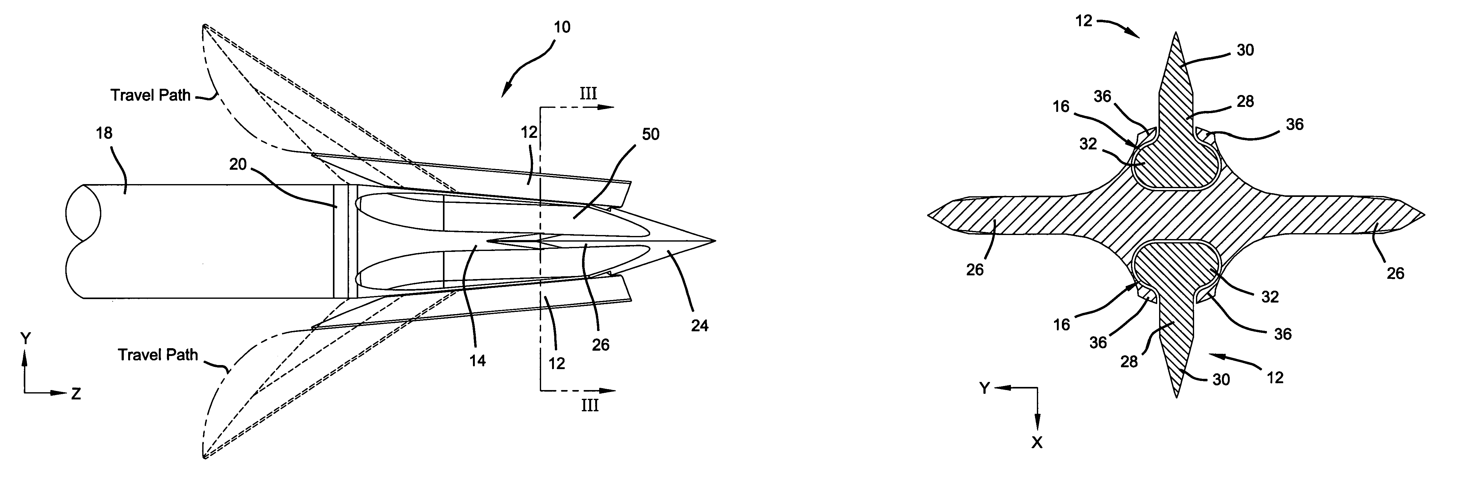
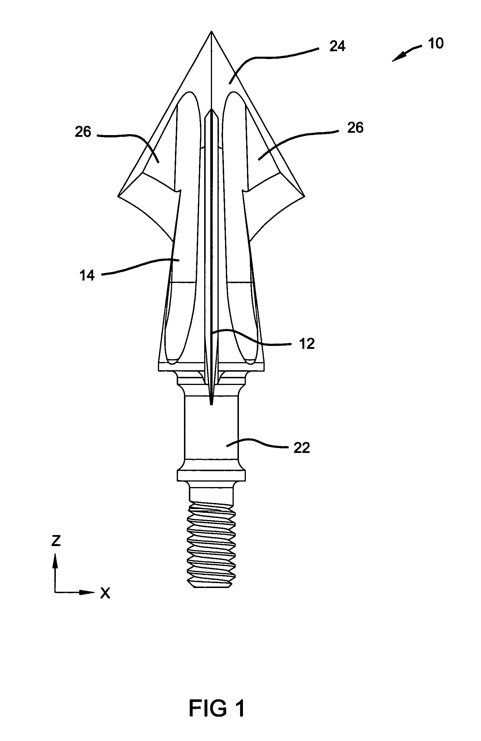
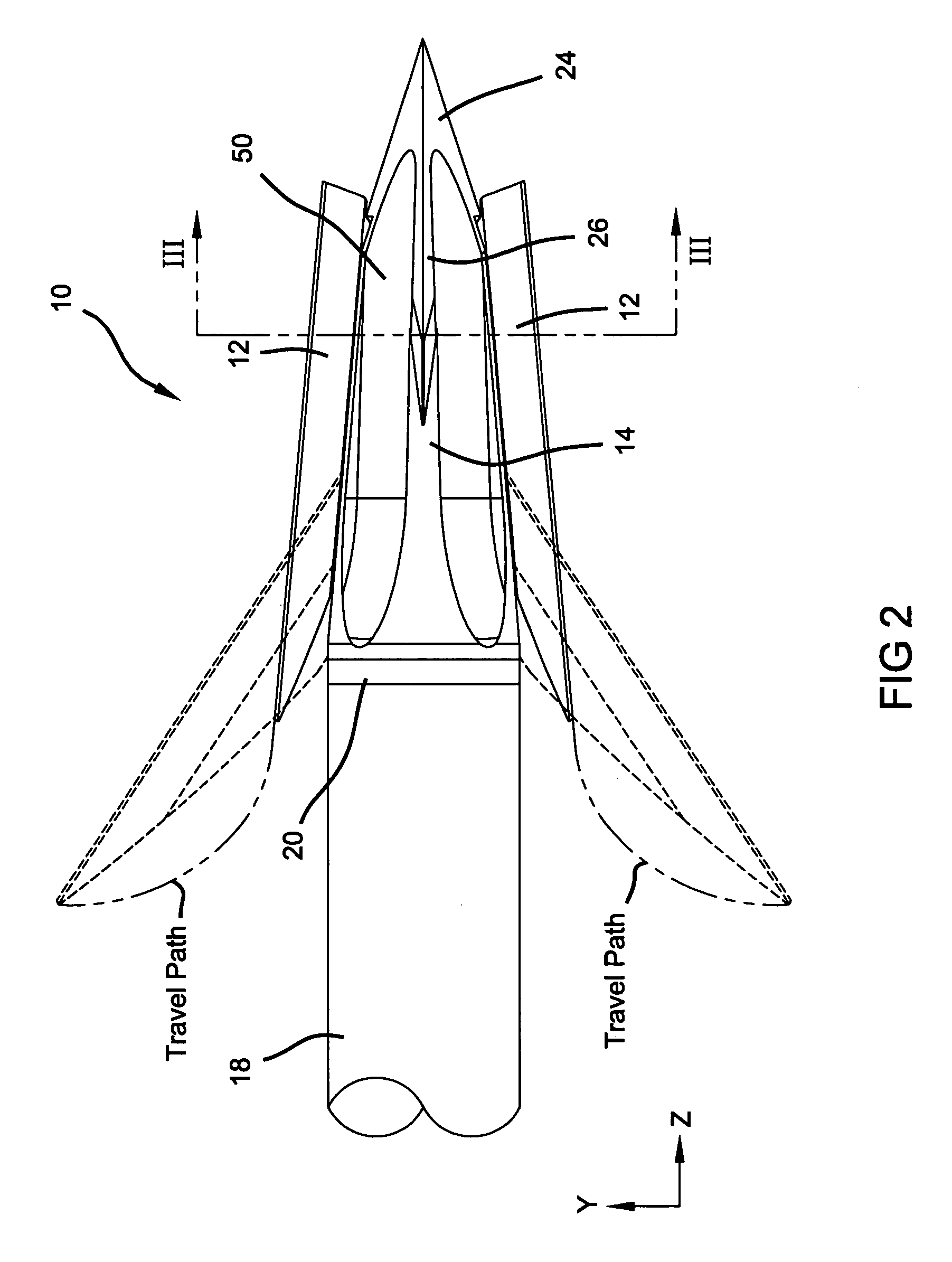
[0025]With reference to the Figures, a first preferred embodiment of the present invention is illustrated in FIGS. 1–7, a second preferred embodiment of the present invention is illustrated in FIGS. 8–10 and a third preferred embodiment is illustrated in FIGS. 12 and 13. Unless specifically noted, it will be understood that the three preferred embodiments share the same or similar features. The present invention is directed to a mechanical broadhead 10 having multiple blades 12 operably coupled to a ferrule 14 such that the blades 12 slide within a channel 16 formed longitudinally in the ferrule 14. Blades 12 are slidably positionable within channel 16 from an in-flight, retracted position to an on-impact, deployed position. The broadhead 10 is secured to an arrow shaft 18 through insert 20. As presently preferred, ferrule 14 has a shank portion 22 with an external thread formed thereon for releasably securing the ferrule 14 to the insert 20. A tip portion 24 is formed on the ferrul...


PUM


Abstract

The present invention provides a mechanical broadhead in which the blades slide within longitudinal channels formed in the ferrule. The blade includes a transverse boss extending from the flanks which are received in a channel formed in the ferrule. A camming surface formed on the inward edge of the blades cooperate with a collar to provide controlled radial movement of the blades as they slide rearwardly within the channel on the ferrule.

Description

FIELD OF THE INVENTION[0001]The present invention relates generally to mechanical or expanding-blade broadheads, and more particularly to a mechanical broadhead in which the blades slide within a longitudinal channel formed in the ferrule.BACKGROUND OF THE INVENTION[0002]A mechanical or expanding-blade broadhead is a type of broadhead in which the blades are operably coupled to the ferrule in a manner to move from an in-flight, retracted position to an on-impact, deployed position. This configuration of a broadhead is beneficial in that it has flight characteristics similar to those of a field point tip and penetration characteristics similar to those of a fixed blade broadhead.[0003]The most popular type of mechanical broadhead has one or more blades located within a slot such that the cutting edge is on the radially inward edge of the blade. The blade is pivotally coupled to the rearward portion of the ferrule so that it may rotate from a retracted position to a deployed position ...

Claims


Application Information

Patent Timeline
Patent Type & Authority Patents(United States)
IPC IPC(8): F42B6/00F42B6/08
CPCF42B6/08
Inventor GRACE, JR., LOUISGRACE, NATHANIEL E.
Owner GRACE ENG
Why Eureka
Try Eureka