Extruded frame member for use in friction stir welding

a technology of friction stir welding and frame member, which is applied in the direction of non-electric welding apparatus, non-disconnectible pipe joints, support, etc., can solve the problems of high manufacturing cost, difficult management of above-stated gaps, and lowering strength, so as to avoid a dent in the welded joint, prevent the generation of dent, and excellent weld

Inactive Publication Date: 2005-08-30
HITACHI LTD
View PDF41 Cites 17 Cited by
  • Summary
  • Abstract
  • Description
  • Claims
  • Application Information

AI Technical Summary

Benefits of technology

[0012]An object of the present invention is to prevent generation of a dent in a joining region when joining two members (e.g., but not limited to, two metal members, such as of aluminum alloy) by a friction stir welding method.
[0013]Another object of the present invention is to provide members, to be joined by friction stir welding, which avoid a dent in the joining region between the joined members.
[0014]Still another object of the present invention is to provide a friction stir welding method, and product manufactured thereby, whereby a dent can be avoided in the joining region between joined members, where the members joined are abutting each other before being joined or even where there is a small gap between the members before they are joined (but the members are adjacent each other).
[0015]The above-stated objects can be attained by a provision where at least one of the members to be joined has a thickened part, in cross section, at the joining region thereof with another member, the thickened part protruding toward the rotary body used to perform the friction stir welding. The rotary body has large and small diameter portions, e.g., made of a material or materials harder than the material of the members to be welded, the small diameter portion first being inserted in the joining region of the members to be joined, during the joining. The members to be joined are positioned adjacent each other, with the thickened part of one member being positioned adjacent the other member to be joined thereto by welding. Where both members have thickened parts, the thickened parts can be positioned adjacent each other in the joining (joint-forming) region, or only one thickened part need be positioned in the joint-forming region. The rotary body is then caused to enter between the two members, in the joining region, with the small diameter portion of the rotary body being inserted into the joint-forming region of the two members and the large diameter portion of the rotary body extending into the thickened part (but not below the thickened part). The rotary body is then moved along the members to be welded, in the joining region, with the rotary body inserted as described in the previous sentence to perform the friction stir welding. Due to provision of the thickened part, at the joint-forming region, a dent (depressed region) at the weld region, in the joined members, can be avoided. By positioning the rotary body such that the large-diameter portion thereof is inserted into the thickened part (overlaps with the thickened part), an excellent weld is achieved, while avoiding a dent in the welded joint. Advantageously, the large-diameter portion of the rotary body does not extend below the protruding portion of the thickened part, while moving the rotary body to perform the friction stir welding.

Problems solved by technology

It is easy to delete the thickened part; however, correcting for the dent needs a putty working, etc., and as a result a high manufacturing cost is caused.
As a result, a lowering in strength is caused, and particularly in a large-scale construction it invites a problem.
The larger the members, the more a management in the above-stated gap becomes difficult (i.e., the more the gap occurs); accordingly, the dent becomes large, and, moreover, a default is generated easily.
Further, even in a case where the dent is not visible, the dent becomes a problem from an aspect of the performance (e.g., strength of the weld).

Method used


Image

  • Extruded frame member for use in friction stir welding
  • Extruded frame member for use in friction stir welding
  • Extruded frame member for use in friction stir welding

Examples


Embodiment Construction

[0041]One embodiment of the present invention, which is an application of the present invention for a car body of railway cars, will be explained referring to FIGS. 1-5.

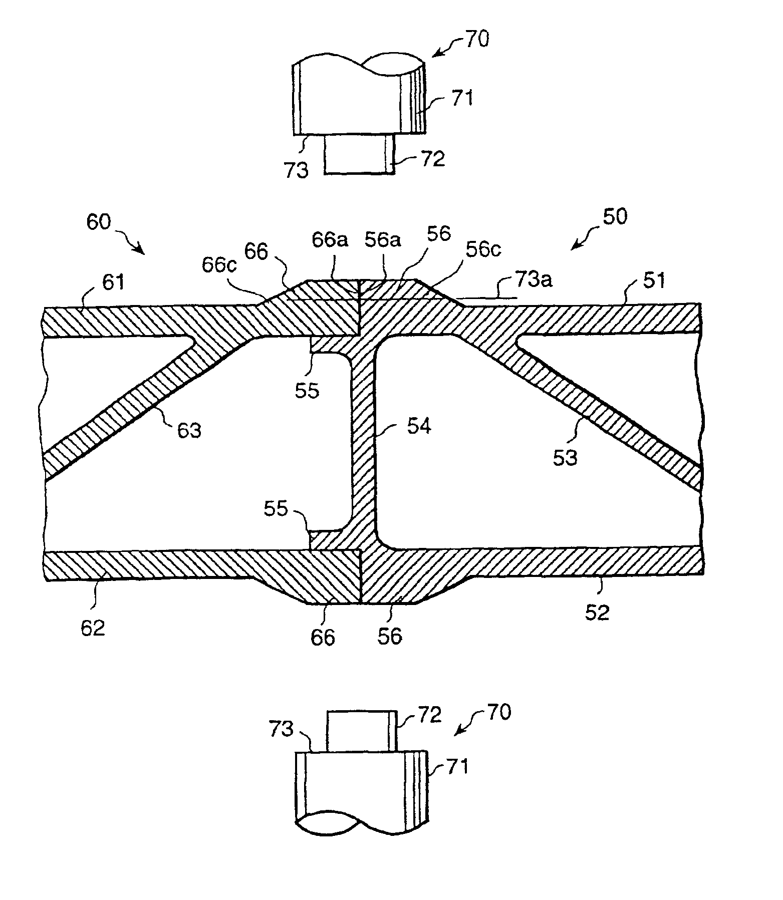
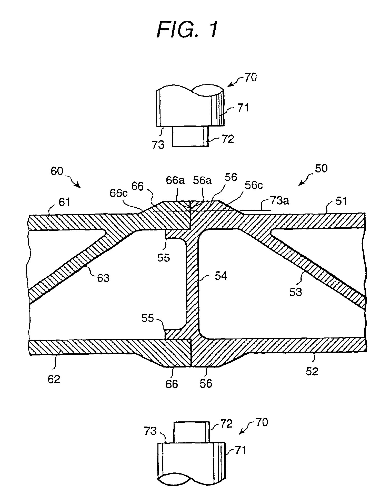
[0042]In FIG. 5, a car body of a railway car is comprised of a side constructive body 41, a roof constructive body 42, a floor constructive body 43, and a constructive body 44 of an end portion at a longitudinal direction. The side constructive body 41 is constituted by arranging plural hollow extruded frame members (50, 60) and by joining contacting portions thereof. The joining is carried out as shown in FIG. 1.

[0043]Each of the roof constructive body 42 and the floor constructive body 43 is constituted similarly. Connections between the side constructive body 42 and the roof constructive body 41 and the floor constructive body 43 are carried out using an MIG (metal electrode inert gas) welding, etc.

[0044]FIG. 1 shows a joint portion of a hollow frame member which constitutes the side constructive body 41. The holl...


PUM

PropertyMeasurementUnit
thicknessaaaaaaaaaa
lengthaaaaaaaaaa
diameteraaaaaaaaaa

Abstract

The friction stir welding technique disclosed avoids occurrence of a dent in adjoining region extending to a level beneath the joined surfaces. At end portions of the frame members to be joined, thickened parts, which project toward the rotary body joining tool, are provided. The Two adjoining thickened parts form a trapezoid shape. The rotary body joining tool has a small-diameter tip portion and a larger diameter portion, and is inserted in the thickened parts. When the rotary body joining tool has been inserted small-diameter tip end first to a level where the larger diameter portion of the rotary body joining tool overlaps the thickened part, the rotary body is rotated and moved along the joining region. Even when a gap exists between two thickened parts, a desirable joining can be carried out. After the joining, the remaining parts of the thickened parts can be machined to form a smooth surface.

Description

[0001]This application is a Divisional application of application Ser. No. 09 / 546,563, filed Apr. 11, 2000, now U.S. Pat. No. 6,237,829 which is a Divisional application of application Ser. No. 09 / 025,070, filed Feb. 17, 1998, now U.S. Pat. No. 6,050,474 the contents of which are incorporated herein by reference in their entirety.BACKGROUND OF THE INVENTION[0002]The present invention relates to a friction stir welding method suitable for use in a joining of members of various materials, including, for example, an aluminum alloy member, etc.[0003]A friction stir welding method is a method in which by rotating a round-shaped rod (a rotary body) inserted in a joining region between two members (e.g., but not limiting, two metal bodies, such as two Al bodies), and further by moving the rotary body along a joining line, the two bodies at the joining region are heated, and material thereof softened and plastically fluidized and thus the two bodies are solid-phase joined, e.g., are welded ...

Claims


Application Information

Patent Timeline
Patent Type & Authority Patents(United States)
IPC IPC(8): B23K20/12B23K37/08B23K33/00B23K103/10B23P23/00B61D17/00B23Q3/155B23Q3/157B61D17/04
CPCB23K20/122B23K33/00B23K37/08B23Q3/15526B23Q3/1576B23K20/126Y10T403/1608B23K2201/045Y10T428/24Y10T428/12493Y10T428/12Y10T428/24479Y10T428/24587Y10T428/2457Y10T428/24612Y10T428/1234Y10T428/12389Y10T403/477Y10T428/12382Y10T428/12375B23K2101/045H05B6/6408
Inventor AOTA, KINYAEZUMI, MASAKUNIISHIMARU, YASUOOKAMURA, HISANORIFUNYUU, ISAOSATOU, AKIHIRO
Owner HITACHI LTD
Why Eureka
Try Eureka