Pulse count motor control device

a technology of motor control and pulse count, which is applied in the direction of vehicle seat, program control, vehicle registration/indication of working, etc., can solve the problems of high inefficiency and cost, difficulty, and requirement for a relatively expensive microprocessor in the control head

Inactive Publication Date: 2005-08-30
APTIV TECH LTD
View PDF21 Cites 11 Cited by
  • Summary
  • Abstract
  • Description
  • Claims
  • Application Information

AI Technical Summary

Problems solved by technology

Due to the large amount of processing, associated drive circuitry, and software required to implement the pulse count control of a motor, this integration through a centralized processor is typically chosen over integrating the drive circuitry into each individual motor as the latter becomes highly inefficient and not cost effective.
However, difficulties arise due to the incorporation of the pulse count processing and motor drive circuitry into a centralized control head.
Returning to the automotive example, the placement of the pulse count processing functions and motor drive circuitry within a central control head leads to the requirement that a relatively expensive microprocessor be used in the control head.
With the addition of the programming and processing requirements called for by the pulse count control system, the processing demands on the control head increase to the point that it requires a relatively powerful, and thus expensive, microprocessor in order for it to carry out its duties.
Beyond hardware costs, the incorporating of the pulse count processing and motor drive circuitry into a centralized control head leads to increased production costs due to the extreme variability between control heads of different vehicles.
As a result, there is no simple and standardized way to incorporate the circuitry and programming of a pulse count control system into a control head.
This results in significant time and expense associated with the process of incorporating a pulse count control system into a vehicle.
This excessive time and effort required to incorporate a pulse count control system into a vehicle also often prevents certain classes of customers from being able to obtain pulse count technology.
For example, due to the wide variances in control heads, a manufacturer of pulse count motor control systems normally has to allocate significant time and resources into engineering a control system for each specific customer.
As a result, it is not economically viable for the manufacturer to allocate the resources for small volume programs or customers.
Thus the manufacturer is restricted in its ability to satisfy the demands of certain customers.

Method used


Image

  • Pulse count motor control device
  • Pulse count motor control device

Examples


Embodiment Construction

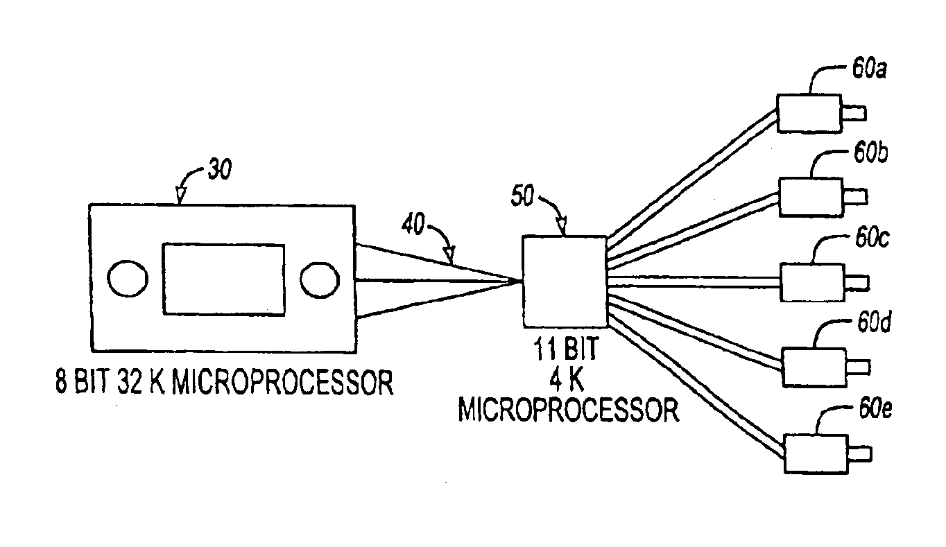
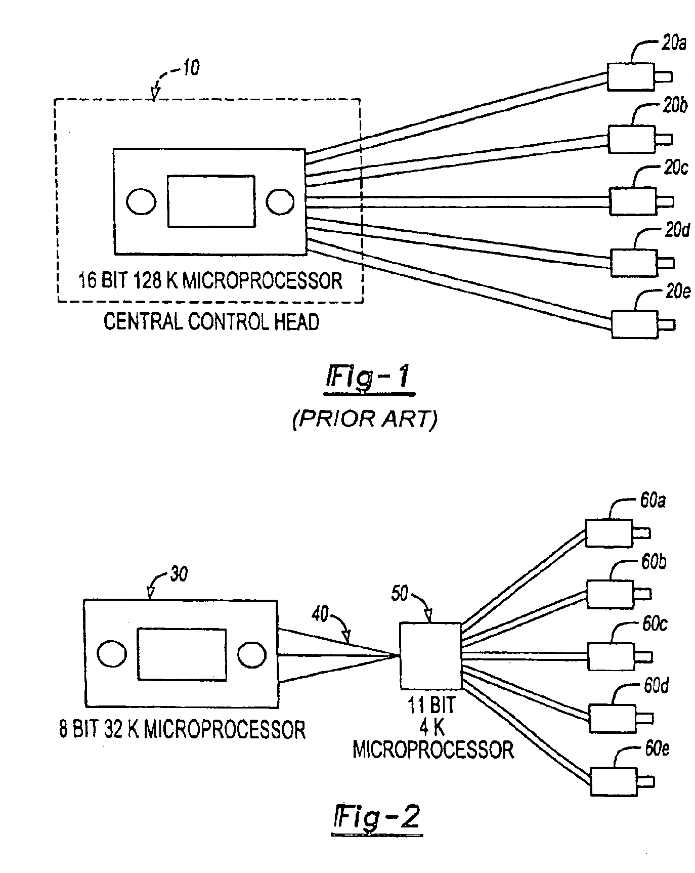
[0010]FIG. 2 illustrates one embodiment of a pulse count motor control system in accordance with the present invention. A central controller or processor 30, such as a control head of an automobile HVAC system, is connected to a pulse count control module 50 through a data bus 40. The control module 50 is then connected to one or more motors 60A-60E whose operation is to be controlled in accordance with pulse count monitoring.

[0011]The data bus 40 can be any type of data communication network or connection allowing bi-directional exchange of information between the central controller 30 and control module 50. For instance, in the automotive HVAC example, data bus 40 could be a serial peripheral interface (SPI) bus or a controller area network (CAN) bus that is frequently used in automobiles.

[0012]In the present example, motors 60A-60E are standard DC motors. However, any type of motor could be utilized in conjunction with the present invention as long as it is compatible with pulse ...


PUM


Abstract

A pulse count motor control device that connects to a central control unit through a first interface and to at least one motor through a second interface. A microprocessor integrated into the motor control device then allows it to directly monitor and drive the motor or motors in accordance with pulse count technology methods.

Description

TECHNICAL FIELD OF THE INVENTION[0001]The present invention relates generally to the precise control of a motor, and, more specifically, to a new device for controlling a motor through pulse count technology.BACKGROUND OF THE INVENTION[0002]Precise control of some motor designs is possible using pulse count technology. According to this position feedback technique, a system monitors brush commutation pulses or current spikes generated during the rotation of the motor. These detected pulses are then appropriately processed and counted, with the results sent to a controller that can then accurately determine and adjust the position of the motor shaft.[0003]Unlike other motor control methods where the drive circuitry is often integrated with each motor, pulse count control is typically implemented through a centralized processor where it can be used to control multiple motors. Due to the large amount of processing, associated drive circuitry, and software required to implement the puls...

Claims


Application Information

Patent Timeline
Patent Type & Authority Patents(United States)
IPC IPC(8): B60H1/00B60N2/02H02P5/68B60W50/00
CPCB60H1/00428B60N2/0232H02P5/68B60W2050/0045G05B2219/2637Y02T10/88B60N2/02246
Inventor HOGAN, MICHAEL PATRICK
Owner APTIV TECH LTD
Why Eureka
Try Eureka