
Focusing aid for camera

Inactive Publication Date: 2005-08-30
MICROSOFT TECH LICENSING LLC
View PDF4 Cites 67 Cited by
  • Summary
  • Abstract
  • Description
  • Claims
  • Application Information

AI Technical Summary

Benefits of technology

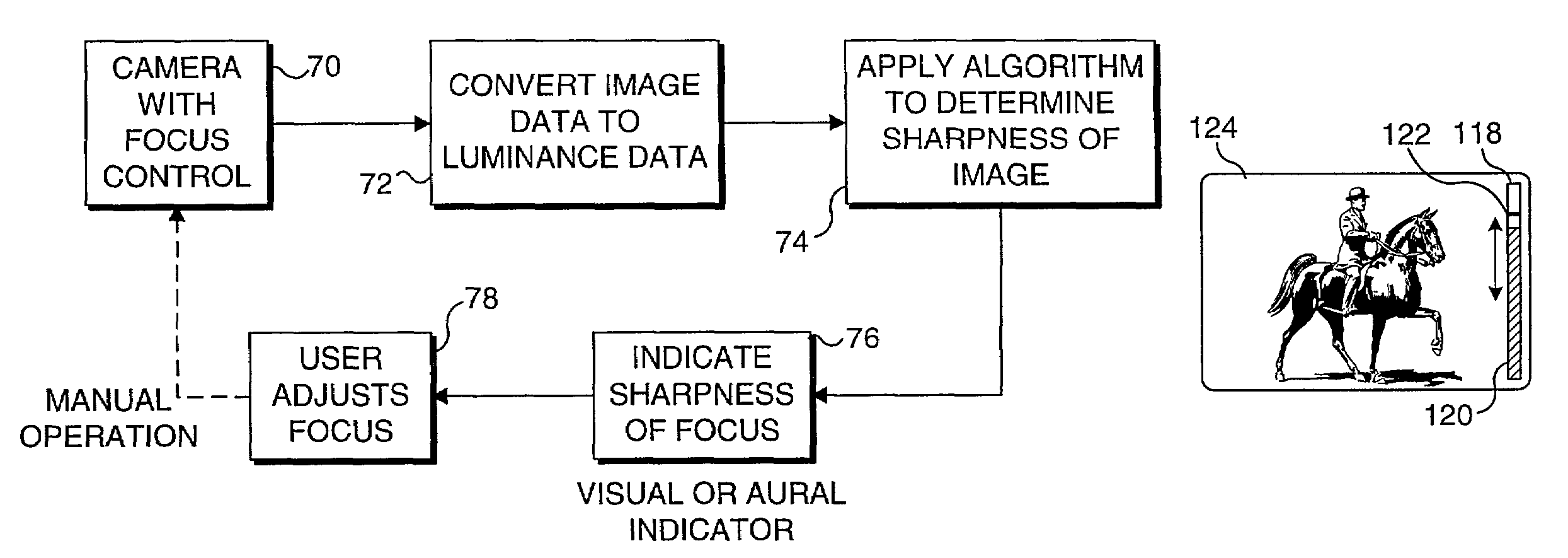
[0006]In accord with the present invention, a method is defined for assisting a user to manually focus a camera. The method includes the step of digitally processing image data produced by the camera to produce a “sharpness value” corresponding to the sharpness of focus of the camera in at least a portion of an image. As the user manually focuses the camera, an indication of the sharpness of focus achieved is then provided to the user as a function of this value, to enable the user to more objectively adjust the focus of the camera.
[0009]In one form of the invention, the step of providing an indication includes the step of displaying a visual indicator corresponding to the sharpness value so that during the step of manually focusing the camera, the user can visually perceive when the sharpest focus is attained by viewing the visual indicator. For example, the visual indicator may comprise a graphical indicator, such as a bar graph showing the current sharpness value. When displaying the visual indicator, the method preferably includes the step of indicating where the sharpness value was at its maximum, which corresponds to the sharpest focus, to enable the user to adjust the focus the camera back to the point of sharpest focus. Alternatively (or in addition to the visible indicator), an audible sound can be provided that is indicative of the current focus so that the user will know when the sharpest focus is achieved, as the user focuses the camera. In such an embodiment, the audible indication may comprise a sound having a varying audible frequency indicative of the sharpness value.

Problems solved by technology

However, to minimize costs, such cameras have relatively few automated controls.
Several factors cause the manual focusing of a PC camera to be very frustrating.
Also, there is inherently a time delay between the point at which an image signal is supplied by a PC camera and the time at which the image is displayed on a monitor.
The delay hinders the manual focusing process.
The time delay between an adjustment and the corresponding effect on the sharpness of the previewed image during the manual focusing process thus makes it difficult to adjust the camera to achieve the sharpest possible image.
Ambient lighting conditions can also adversely impact the user's ability to properly focus a camera.
For example, a poorly lighted scene will result in an image with little contrast, causing the sharpness of the focus to be difficult to visually determine.
Sunlight or other lighting conditions that cause glare on the computer monitor on which the preview image is being viewed can also interfere with the focus adjustment.
Although conventional through-the-lens focusing systems and automated focusing features might be provided on a PC camera, the components required for these solutions to the problem are too expensive to implement at the desired price levels of PC cameras.

Method used


Image

  • Focusing aid for camera
  • Focusing aid for camera
  • Focusing aid for camera

Examples


embodiment

Camera Implemented Embodiment

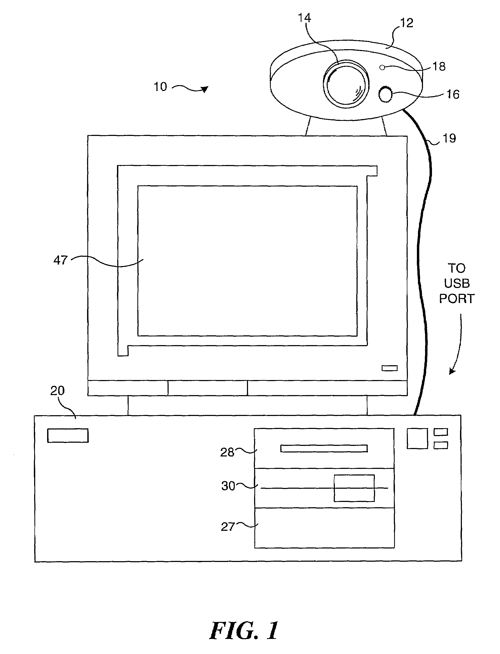
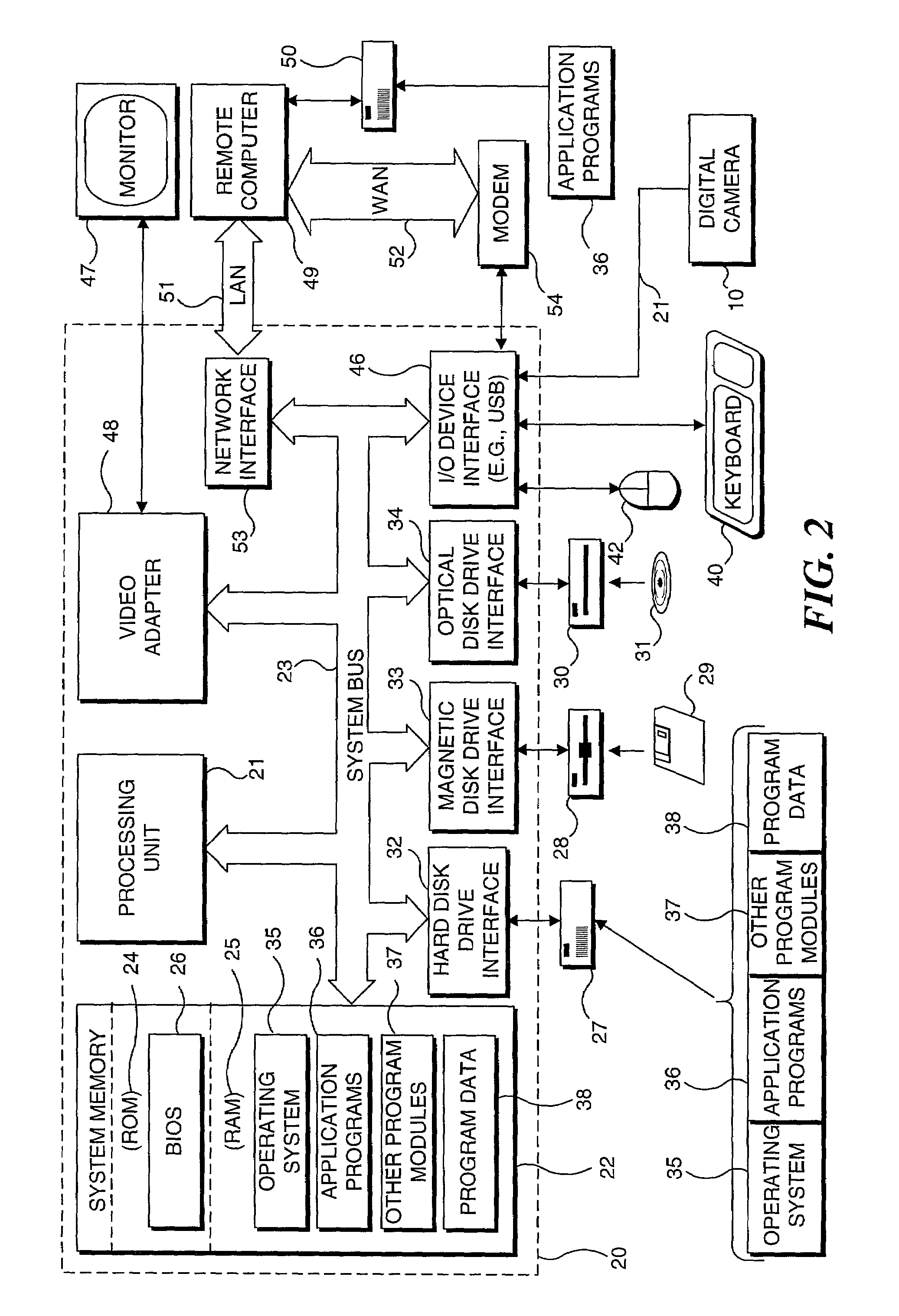
[0055]From the preceding discussion of FIGS. 8A–8D, it will be apparent that a visual indication provided on monitor 47 of PC 20 was employed to assist the user in achieving the sharpest possible focus of PC camera 10 (shown in FIG. 1). The algorithm used to determine the sharpness of focus is in this case carried out as PC 20 executes corresponding software instructions stored in memory, which also cause the PC to display bar graph 134 and maximum indication 136. However, it is also contemplated that this or other appropriate algorithm used to determine the sharpness of focus can instead be implemented by a processor included within a camera and that a visual or aural indication of the sharpness of focus can be provided to a user of the camera without need for an algorithm to executed by a host computing device. In this case, the camera can be used in a standalone mode, without being coupled to a PC or other host computing device, or even if so coupled,...


PUM


Abstract

An indication of sharpness of focus is provided to a user to assist in focusing a camera. In one embodiment, the camera is coupled to a personal computer. An algorithm is implemented by the personal computer to determine a sharpness of focus based upon differences between the luminance of adjacent pixels in a selected region of an image produced by the camera. A visual or aural indication of the sharpness of focus is provided to the user to enable the user to focus the camera to the sharpest possible focus. Alternatively, the algorithm can be implemented by a processor within a camera so that a visual or aural indicator on the camera provides the indication of sharpness of focus as a user adjusts the focus of the camera.

Description

FIELD OF THE INVENTION[0001]The present invention generally relates to a method and system for determining when a camera is properly focused, and more specifically, to assisting a user to manually adjust the focus of a camera by providing an indication of the sharpness of focus of the camera.BACKGROUND OF THE INVENTION[0002]Broadband access to the Internet has greatly increased the demand for digital video cameras designed for use with a personal computer (PC). These video cameras, which are also known as Webcams, are connected to a PC and used to produce compressed streaming video data for transmission over the Internet, local area, and / or wide area networks. While early cameras of this type were only capable of producing black and white images, the development of low cost transistor-based, i.e., complementary metal oxide semiconductor (CMOS), imaging sensors has enabled reasonably good color images to be produced by PC cameras, although typically at less than full motion frame rat...

Claims


Application Information

Patent Timeline
IPC IPC(8): H04N5/232
CPCH04N5/23212H04N23/661H04N23/673H04N23/635
Inventor SINGH, HARJITKILZER, ROBERT T.
Owner MICROSOFT TECH LICENSING LLC
Learn More