

Method and device for image display
a technology for image display and image, applied in the direction of lighting support devices, instruments, television systems, etc., can solve the problems of difficulty in obtaining a good view of the site of the operation, unable to provide any depth information, and surgeons find it difficult to work with the required precision
- Summary
- Abstract
- Description
- Claims
- Application Information
AI Technical Summary
Benefits of technology
Problems solved by technology
Method used
Image

Examples
Embodiment Construction
[0007]These objects are achieved according to the invention by use of a method that has the characteristics described in claim 1 and also by means of a device that has the characteristics described in claim 10.
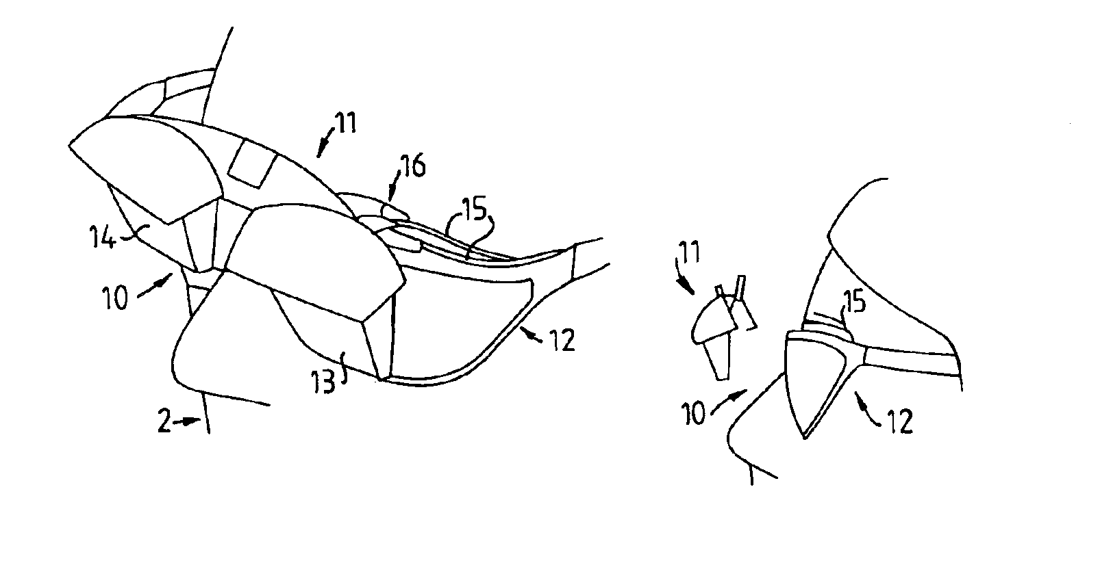
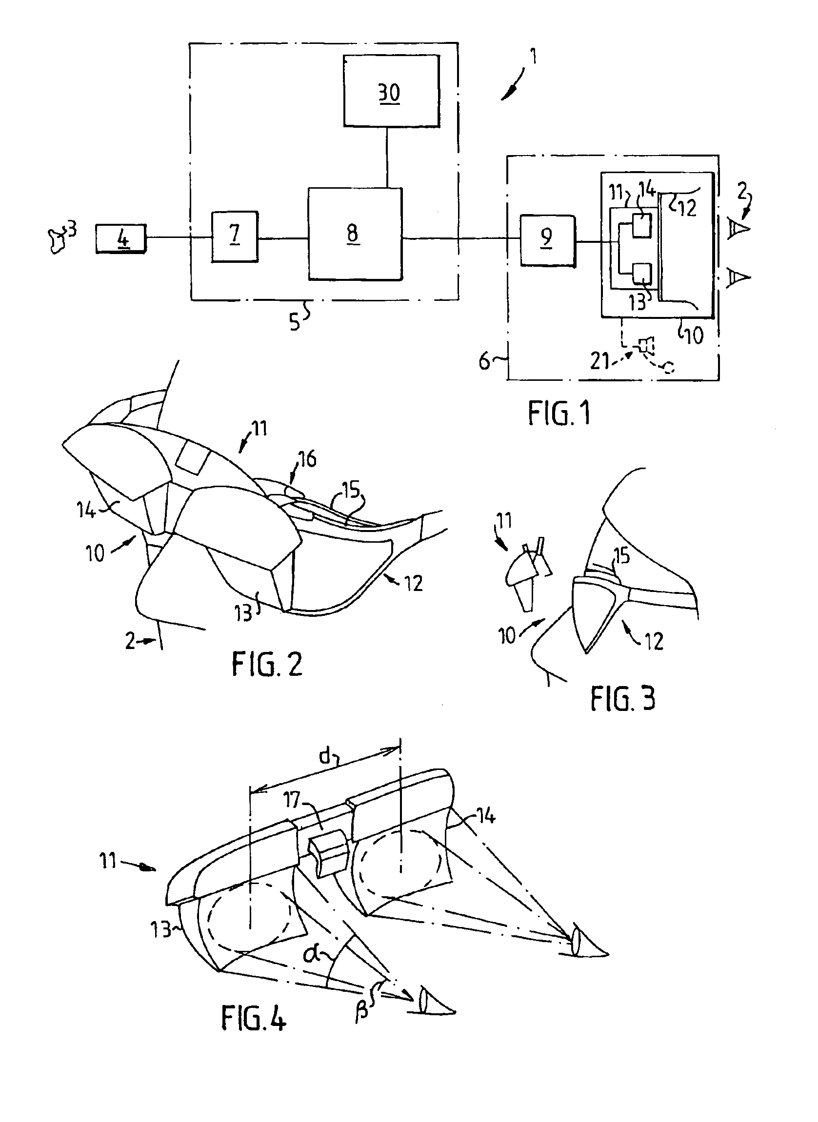
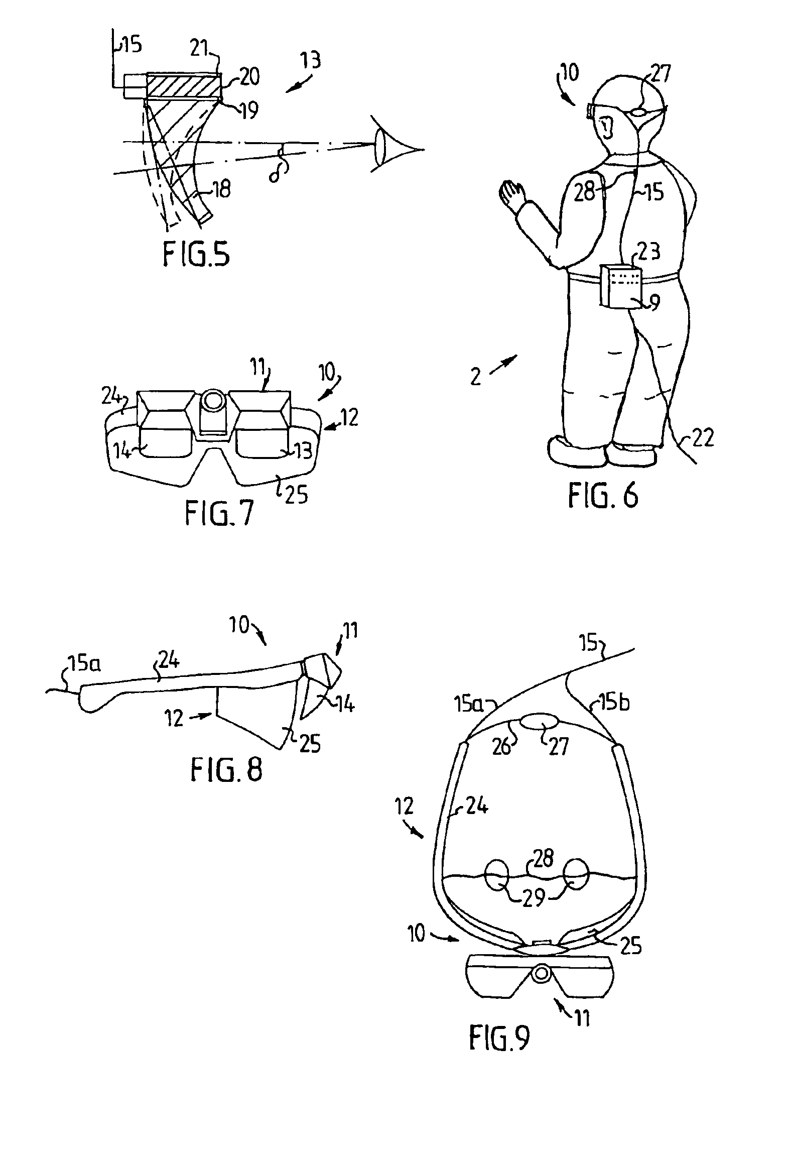
[0008]By using head-mounted equipment, where an image is projected in front of each eye, it is possible to create a perception of depth in the image, with the image at the required distance in front of the eyes. By also letting each of these image display positions take up a relatively limited part of the user's total field of vision, it is possible to achieve a free view both above and below the equipment and to the sides, which contributes to a great extent to allowing the user to retain a good orientation in the space where the equipment is used, which is particularly important during prolonged periods of work.
[0009]In addition, according to the invention, equipment is obtained that is easy to adapt to fit different individuals by changing one or more components, without al...
PUM
 Abstract
Description
Claims
Application Information