Leakage nulling receiver correlator structure and method for ultra wide bandwidth communication system

a communication system and receiver technology, applied in the field of leakage null receiver correlator structure and method, can solve the problems of dc offset (or bias) from the leakage current provided at the output of the mixer, and the receiver correlator structure is difficult to achieve, and the bias propagates as noise through the rest of the receiver

Inactive Publication Date: 2005-08-30
NORTH STAR INNOVATIONS
View PDF13 Cites 31 Cited by
  • Summary
  • Abstract
  • Description
  • Claims
  • Application Information

AI Technical Summary

Benefits of technology

[0025]It is an object of the present invention to eliminate the DC component of signal IF yet optimally detect a long stream of logical “1”''

Problems solved by technology

Moreover, the value of signal LO is relatively large (being typically in the range of volts) compared to the value of signal RF (being typically in the range of microvolts), making it difficult for receiver correlator structure 10 to distinguish between signal LO and signal RF after signals LO and RF are mixed by mixer 14.
A problem with the ultra wide bandwidth receivers of the related art is that the mixer may transmit a leakage current from the local oscillator signal (which is typically in the range of microvolts) to the inp

Method used


Image

  • Leakage nulling receiver correlator structure and method for ultra wide bandwidth communication system
  • Leakage nulling receiver correlator structure and method for ultra wide bandwidth communication system
  • Leakage nulling receiver correlator structure and method for ultra wide bandwidth communication system

Examples


Embodiment Construction

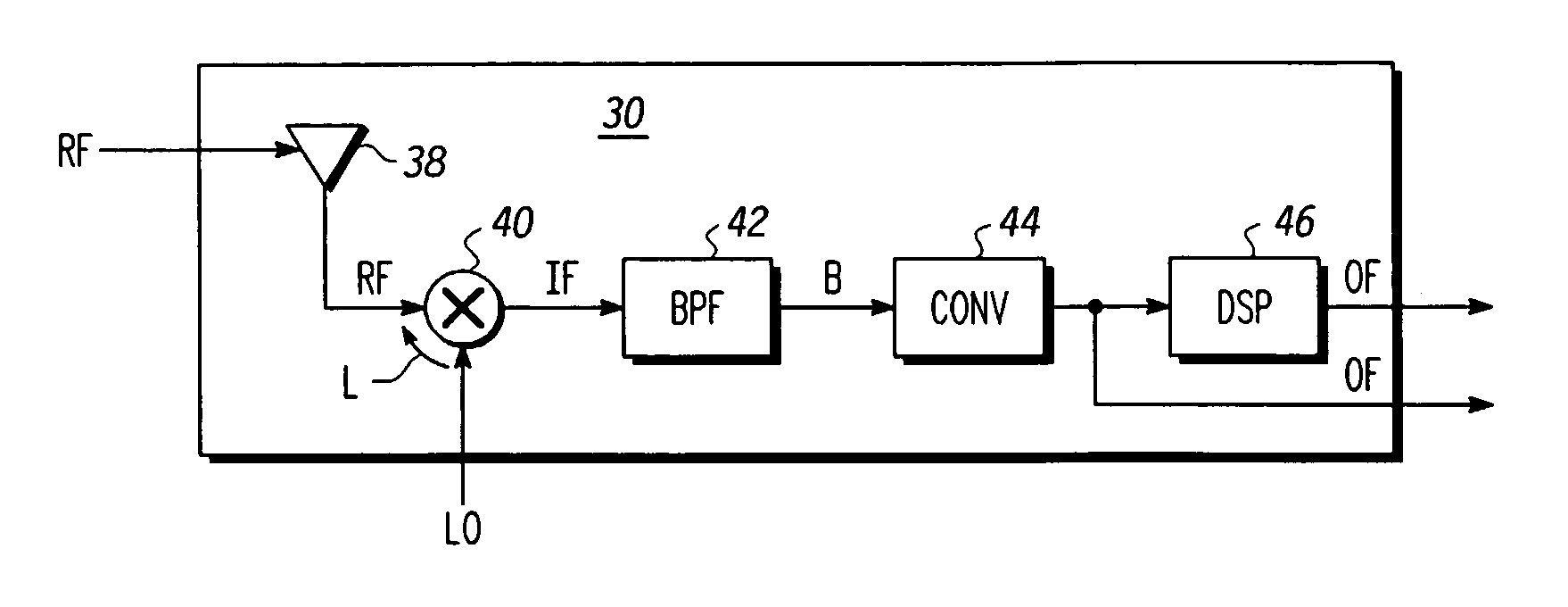
[0055]FIG. 6 shows a receiver correlator 30 of the present invention which receives from transmitter 32 an ultra wide bandwidth signal RF. Ultra wide bandwidth signal RF comprises a sequence of wavelets of particular shapes and positions. Transmitter 32 is disclosed in Ser. No. 09 / 685,205, filed Oct. 10, 2000, entitled SYSTEM AND METHOD FOR GENERATING ULTRA WIDEBAND PULSES, incorporated herein by reference, and in Ser. No. 09 / 685,197 filed Oct. 10, 2000, entitled ULTRA WIDEBAND COMMUNICATION SYSTEM WITH LOW NOISE PULSE FORMATION, incorporated herein by reference.

[0056]In addition, the receiver correlator structure 30 of the present invention receives an ultra wide bandwidth signal LO. Ultra wide bandwidth signal LO comprises a sequence of wavelets of particular shapes and positions corresponding to ultra wide bandwidth signal RF. Ultra wide bandwidth signal LO is produced by timing generator 36 as disclosed in co-pending Application Ser. No. 09 / 685,199 filed Oct. 10, 2000, entitled ...


PUM


Abstract

A receiver correlator structure for an ultra wide bandwidth communication system includes an antenna, a mixer, a bandpass filter, and a convertor. The receiver receives, via the antenna, an ultra wide bandwidth signal comprising a sequence of wavelets of particular shapes and positions, and transmits the received ultra wide bandwidth signal to the mixer. The mixer also receives and mixes with the received ultra wide bandwidth signal a local ultra wide bandwidth signal comprising a sequence of wavelets of particular shapes and positions correlated to the received ultra wide bandwidth signal. The bandpass filter removes the DC components from the mixed signal, and provides the resultant signal to the convertor. The receiver structure eliminates the local ultra wide bandwidth signal AC bias and DC bias terms and 1/f noise, yet detects long sequences of logical 1's and 0's, and allows operation with reduced bandwidth convertors.

Description

CROSS REFERENCE TO RELATED APPLICATION[0001]The present document contains subject matter related to that disclosed in the following commonly owned, U.S. patent applications: Ser. No. 09 / 209,460 filed Dec. 11, 1998, entitled ULTRA WIDE BANDWIDTH SPREAD-SPECTRUM COMMUNICATIONS SYSTEM, now issued as U.S. Pat. No. 6,700,939; Ser. No. 09 / 633,815 filed Aug. 7, 2000 entitled ELECTRICALLY SMALL PLANAR UWB ANTENNA; Ser. No. 09 / 563,292 filed May 3, 2000 entitled PLANAR UWB ANTENNA WITH INTEGRATED TRANSMITTER AND RECEIVER CIRCUITS, now issued as U.S. Pat. No. 6,351,246; Ser. No. 60 / 207,225 filed May 26, 2000 entitled ULTRA WIDE BANDWIDTH SPREAD SPECTRUM COMMUNICATIONS SYSTEM; Ser. No. 09 / 685,198 filed Oct. 10, 2000 entitled ANALOG SIGNAL SEPARATOR FOR UWB VERSUS NARROWBAND SIGNALS; Ser. No. 60 / 238,466 filed Oct. 10, 2000, entitled ULTRA WIDE BANDWIDTH NOISE CANCELLATION MECHANISM AND METHOD; Ser. No. 60 / 217,099 filed Jul. 10, 2000, entitled MULTIMEDIA WIRELESS PERSONAL AREA SYSTEM NETWORK (WPA...

Claims


Application Information

Patent Timeline
IPC IPC(8): H04L25/06H04B1/69H04L27/00
CPCH04B1/71637H04B1/7172H04L25/061H04L27/0004H04B1/709
Inventor MCCORKLE, JOHN W.
Owner NORTH STAR INNOVATIONS
Why Eureka
Try Eureka