Image coding apparatus

a technology of image coding and coding apparatus, which is applied in the field of image coding apparatus, can solve the problems of unavoidable and achieve the effect of reducing the number of bits generated and minimizing the deterioration of image quality

Inactive Publication Date: 2005-08-30
SOVEREIGN PEAK VENTURES LLC
View PDF18 Cites 50 Cited by
  • Summary
  • Abstract
  • Description
  • Claims
  • Application Information

AI Technical Summary

Benefits of technology

[0005]It is therefore an object of the present invention to provide an image coding apparatus that can greatly cut down on the number of bits generated while minimizing the deterioration in image quality.

Problems solved by technology

Accordingly, deterioration of image quality is unavoidable in such a situation.

Method used


Image

  • Image coding apparatus
  • Image coding apparatus
  • Image coding apparatus

Examples


embodiment 1

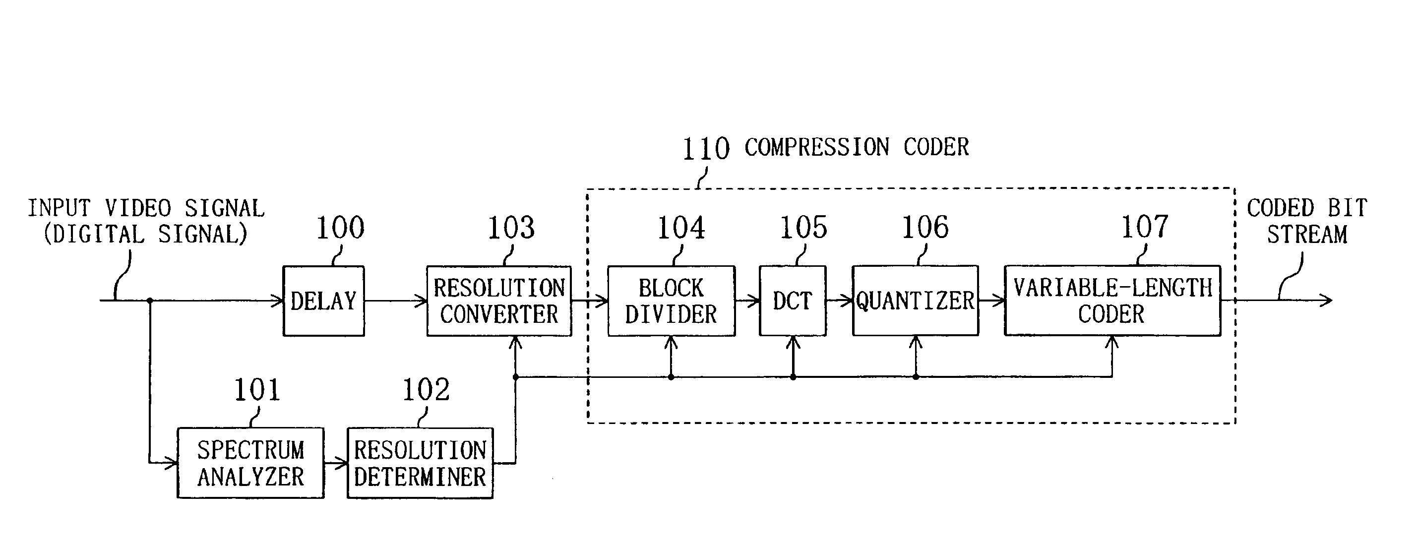
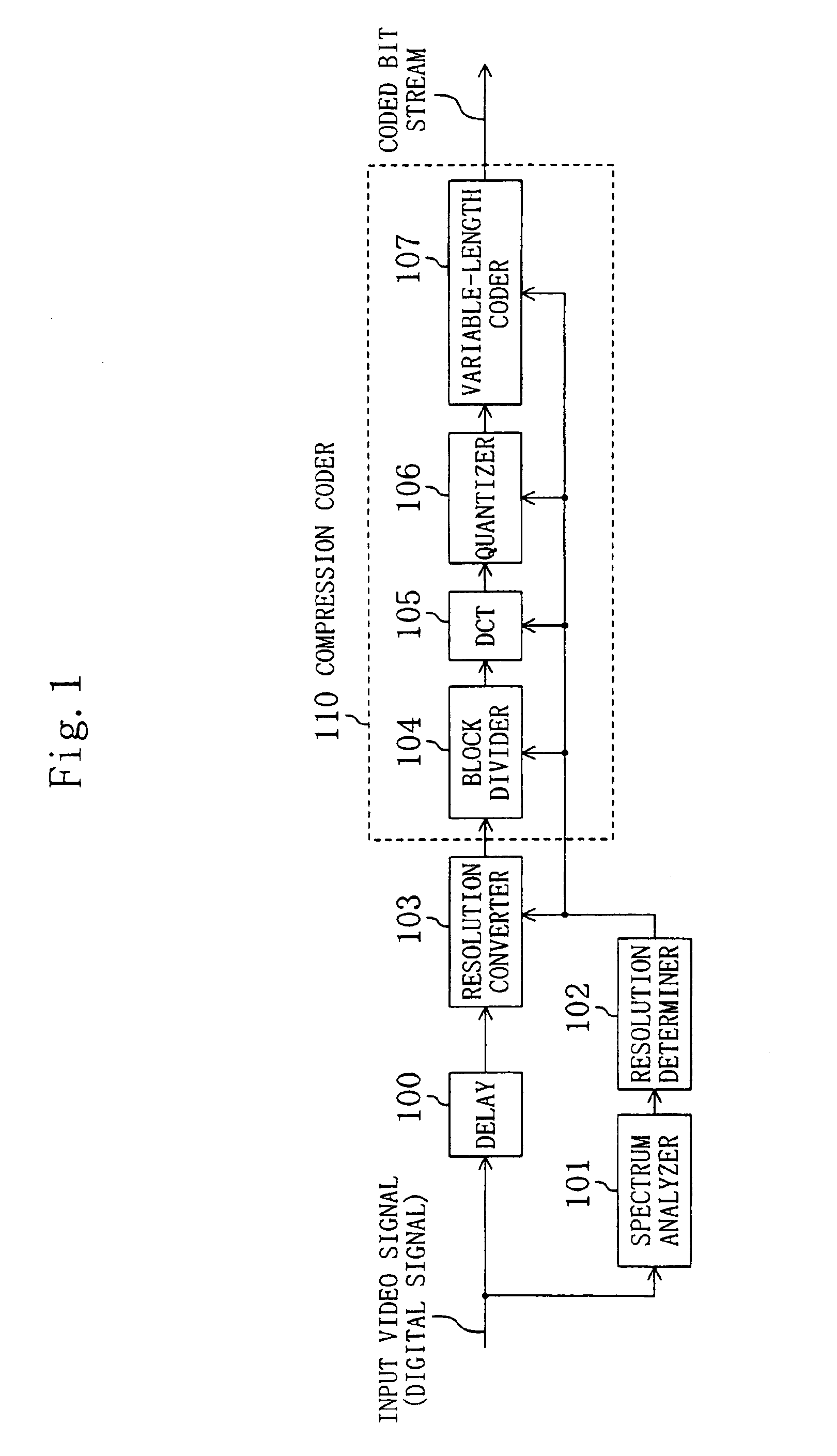
[0049]A first embodiment of the present invention will be described with reference to FIG. 1. FIG. 1 illustrates an image coding apparatus including delay device 100, spectrum analyzer 101, resolution determiner 102, resolution converter 103 and compression coder 110. The compression coder 110 is made up of block divider 104, DCT transformer 105, quantizer 106 and variable-length coder 107. A block arrangement, which is specially designed for intra-frame coding, is illustrated in FIG. 1 for the sake of simplicity.

[0050]First, a digital video signal is input to the spectrum analyzer 101. The spectrum analyzer 101 transforms a video frame from a spatial domain into a frequency domain, which is implementable by performing a Fourier transform on the video signal, for example. This transformation may be carried out either on the entire frame or on a block or macroblock basis by dividing each frame into multiple units that are approximately equal in size to blocks or macroblocks. Then, th...

embodiment 2

[0059]A second embodiment of the present invention will be described with reference to FIG. 6. FIG. 6 illustrates an image coding apparatus including delay device 100, filters 201, 202, output value comparators 204, 205, resolution determiner 207, resolution converter 103 and compression coder 110.

[0060]First, a digital video signal is input to the filters 201 and 202, which are low-pass filters with mutually different cutoff frequencies. FIG. 7 illustrates exemplary frequency characteristics of the filters 201 and 202. As shown in FIG. 7, the cutoff frequency fc2 of the filter 202 is higher than that fc1 of the filter 201 in the illustrated example. The outputs of the filters 201 and 202 are input to the output value comparators 204 and 205, respectively.

[0061]Receiving these filtered outputs, the comparators 204 and 205 calculate the respective energy values of the filtered output signals, compare these energy values to a predefined threshold value and then output the comparison r...

embodiment 3

[0068]A third embodiment of the present invention will be described with reference to FIG. 10. FIG. 10 illustrates an image coding apparatus including delay device 100, activity calculator 301, resolution determiner 302, resolution converter 103 and compression coder 110.

[0069]First, a digital video signal is input to the activity calculator 301, which calculates the activity of the video frame. As used herein, the “activity” means a variance of pixel values within a frame. Suppose a frame composed of a number N of pixels arranged in the number N of lines, in which i is a horizontal pixel location, j is a vertical pixel location and Pij is a pixel value. In this case, a mean Pm and a variance var are given by

Pm=(1 / N2)ΣΣPij

 var=(1 / N2)ΣΣ(Pij−Pm)2

where ΣΣ is an operation of obtaining a sum of squared deviations from the mean Pm with respect to i between 0 and N−1 and to j between 0 and N−1. Then, the activity calculator 301 outputs the activity calculated. Optionally, the activity may ...


PUM


Abstract

A video frame is input to a spectrum analyzer, which transforms the frame from a spatial domain into a frequency domain. A resolution determiner analyzes the output of the spectrum analyzer, thereby selecting a resolution appropriate for the video frame. Then, a resolution converter converts a resolution of the video frame into the resolution selected by the resolution determiner. Thereafter, the video frame is subjected to a coding process by block divider, DCT transformer, quantizer and variable-length coder so as to be output as a coded bit stream. By coding the input video frame at a resolution corresponding to the high-frequency component in the frame, a video of higher quality can be obtained with the bit rate reduced.

Description

[0001]This application is a division of U.S. patent application Ser. No. 09 / 588,186 filed Jun. 7, 2000 now U.S. Pat. No. 6,625,322.BACKGROUND OF THE INVENTION[0002]The present invention relates to an image coding apparatus for compressing and coding a video signal.[0003]MPEG-2 is known as one of the high-efficiency video compression standards issued by Moving Picture Experts Group. In accordance with the MPEG-2 standard, each video frame (or field) is classified as an I, P or B frame. An I-frame is intra-frame coded using no reference frames. On the other hand, P- and B-frames are inter-frame predictively coded using some reference frames. Specifically, a P-frame is an abbreviation of a predictively coded frame, which is also called a “predicted frame”, A B-frame means a bidirectionally coded frame, which is also called a “bidirectionally predicted frame”, Each frame is also subdivided into a plurality of units called “macroblocks”, each of which is composed of 16×16 pixels. And eac...

Claims


Application Information

Patent Timeline
Patent Type & Authority Patents(United States)
IPC IPC(8): G06T9/00H04N7/26H04N7/50H04N7/46G06K9/36H04N7/30
CPCH04N19/176H04N19/172H04N19/15H04N19/115H04N19/61H04N19/60H04N19/107H04N19/114H04N19/132H04N19/14H04N19/142H04N19/162H04N19/18H04N19/182H04N19/179H04N19/85H04N19/87H04N19/59H04N19/152
Inventor KONDO, SATOSHIKAWASAKI, KOJIROFUKUDA, HIDEKINAKAMURA, KAZUHIKOIWASAKI, SHIRO
Owner SOVEREIGN PEAK VENTURES LLC
Why Eureka
Try Eureka